Method for adding metal redundant graph

A redundant pattern and metal technology, applied in the field of lithography, can solve the problems of large difference in AEICD of metal lines, inability to achieve metal density and density gradient, etc., to reduce the difference and improve the uniformity of line width.

Inactive Publication Date: 2020-05-26
SHANGHAI INTEGRATED CIRCUIT RES & DEV CENT
View PDF2 Cites 0 Cited by
  • Summary
  • Abstract
  • Description
  • Claims
  • Application Information

AI Technical Summary

Problems solved by technology

[0004] However, with the continuous shrinking of the feature size of integrated circuits, the key dimensions of the device are also getting smaller and smaller, and the metal line width (metal line width) and spacing (space) are also becoming smaller and smaller. After the metal line width and spacing are reduced, The traditional method of adding metal redundant patterns often still cannot meet the requirements of metal density and density gradient, resulting in a large difference in the AEI CD of the same metal line in different density areas

Method used


Image

  • Method for adding metal redundant graph
  • Method for adding metal redundant graph
  • Method for adding metal redundant graph

Examples


Embodiment 1

[0048] A method for adding a metal redundancy pattern provided in this embodiment includes the following steps:

[0049] S01: as attached figure 1 As shown, the original layout is provided, and the original layout includes a metal layer composed of metal lines, a via hole between metal layers, a via hole in an active area, and a metal redundant pattern barrier layer.

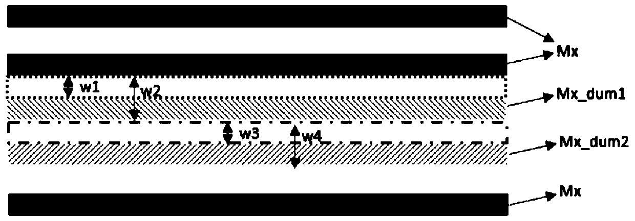
[0050] S02: Find the metal line Mx with a line width of 50nm through layout logic operation, and screen out the metal edge with a distance greater than 210nm from the adjacent metal lines with different potentials from the metal lines with a line width of 50nm.

[0051] S03: as attached figure 2 As shown, expand the metal side by W 1 = 80nm and W 2 =130nm, form polygons m1 and m2, through logic operation, draw the overlapping part of polygons m1 and m2, be the temporary metal redundant figure Mx_dum1; width.

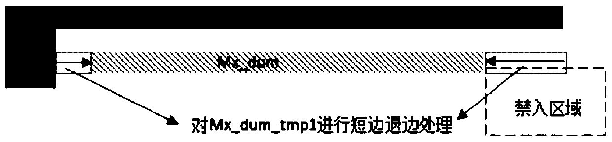
[0052] S04: Perform post-processing on the temporary metal redundancy figure Mx_dum1 to obtain th...


PUM


Abstract

The invention discloses a method for adding a metal redundant graph. The method comprises the following steps of S01, providing an original layout; S02, finding out a metal edge of which the distanceto an adjacent metal wire is greater than or equal to a distance threshold in the metal wires through layout logic operation; S03, respectively expanding the metal edges outwards by W1 and W2 to formpolygons m1 and m2, and obtaining an overlapped part of the polygons m1 and m2 through logical operation, namely a temporary metal redundant graph; S04, carrying out post-processing on the temporary metal redundant graph to obtain a to-be-added metal redundant graph; and S05, finding out the metal edges of which the distances to the adjacent metal lines are greater than or equal to a distance threshold in the metal redundant graph in the step S04 through layout logic operation, and repeating the steps S03-S04N times to complete the addition of the metal redundant graph in the original layout.According to the method for adding the metal redundant pattern, the uniformity of the line width after the small-line-width metal line is etched is greatly improved, and the difference of the metal line AEI CD is reduced.

Description

technical field [0001] The invention relates to the field of photolithography, in particular to a method for adding metal redundant patterns. Background technique [0002] The processes that have the greatest impact on line width control in the semiconductor manufacturing process include lithography and etching. The line width after lithography depends not only on the performance parameters and process conditions of the lithography machine itself, but also by means of optical proximity correction (OPC) To improve line width uniformity and increase the photolithography process window. The line width after etching (AEI CD, After Etching Inspection Critical Dimension) is not only affected by the line width after photolithography and the photoresist profile, but also by the loading effect between the high and low density areas of the pattern. The photoresist in the low-density graphic area is less, which can react with more etchant, resulting in higher etching rate and more etc...

Claims


Application Information

Patent Timeline
Patent Type & Authority Applications(China)
IPC IPC(8): G06F30/392
Inventor 张美丽
Owner SHANGHAI INTEGRATED CIRCUIT RES & DEV CENT
Why Eureka
Try Eureka