Intake and exhaust system of turbine engine

A turbine engine and exhaust system technology, which is applied in the field of turbo fracturing, can solve the problems of small intake area, loud noise, damage to the turbine engine, etc., to reduce the intake flow rate, ensure air quality, and increase the intake area Effect

Pending Publication Date: 2020-05-29
美国杰瑞国际有限公司
View PDF9 Cites 114 Cited by
  • Summary
  • Abstract
  • Description
  • Claims
  • Application Information

AI Technical Summary

Problems solved by technology

The reasonable performance of the intake and exhaust system of the turbine fracturing equipment affects the operation of the turbine engine, which in turn affects the operation progress of the entire fracturing site
On the one hand, the air intake demand of a turbine engine is very large, several times that of an ordinary diesel engine. The air intake area of ​​the existing turbine engine is relatively small. To meet the air intake demand of the turbine engine, under the premise of a small air intake area, The air intake speed must be high, because there are many solid suspended particles and silica dust in the air, which will reduce the life of the air intake air filter
On the other hand, the turbine engine will produce very loud noises, so the noise reduction treatment of the exhaust muffler is required, and the exhaust muffler is usually designed to connect the exhaust port and the air intake port due to the limitation of the height of the vehicle-mounted equipment. The horizontal height is equal. Although this method meets the height requirements of the vehicle equipment, the exhaust gas discharged from the exhaust port is easily inhaled by the intake port, which affects the oxygen content of the intake air, and the exhaust on the exhaust port is silenced. The exhaust muffler is an open type. If it rains, the rainwater will be deposited in the exhaust muffler, and more seriously, it will flow back into the turbine engine and damage the turbine engine.

Method used


Image

  • Intake and exhaust system of turbine engine
  • Intake and exhaust system of turbine engine

Examples


Embodiment Construction

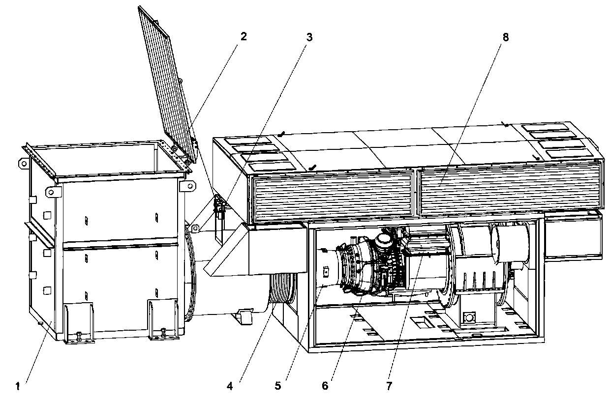
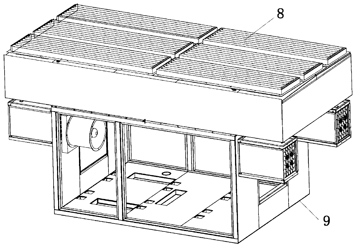
[0018] Such as Figures 1 to 2 Shown, a kind of intake and exhaust system of turbine engine comprises intake system and exhaust system, and described intake system is connected with the intake port of turbine engine 6, and described exhaust system is connected with the exhaust port of turbine engine 6 connected, the air intake system includes an air intake filter 7 and an air intake pipe 8, one end of the air intake filter 7 and the air intake pipe 8 is connected, and the other end of the air intake pipe 8 is connected to the air intake of the turbine engine 6 connected, the intake filter 7 adopts a "V" structure, and the "V" structure, that is, the cross-sectional shape of the intake filter 7 is "V", which increases the intake area and satisfies the requirements of the turbine engine. 6 Large air intake requirements At the same time, the intake flow rate is reduced, the damage to the air filter by dust and particulate matter in the air is avoided, and the service life of the ...


PUM


Abstract

The invention discloses an intake and exhaust system of a turbine engine. The intake and exhaust system of the turbine engine comprises an intake system and an exhaust system, wherein the intake system is connected with an intake port of the turbine engine, the exhaust system is connected with an exhaust port of the turbine engine, the intake system comprises an intake filter and an intake pipeline, the intake filter is connected with the intake pipeline, the intake filter adopts a V-shaped structure, and a rain shielding cap is arranged at the exhaust tail end of the exhaust system. The intake and exhaust system of the turbine engine has the beneficial effects that the air inlet area is large, the air inlet flow speed is lower, the service life of an air filter is long, the rain shieldingcap additionally arranged at the exhaust port avoids the rainwater deposition in an exhaust silencer, the condition that rainwater possibly flows backwards is avoided and damages the turbine engine,and an opening of the rain shielding cap is away from the intake port, so that exhausted waste gas is prevented from being sucked by the intake port, and the quality of inlet air is ensured.

Description

technical field [0001] The invention relates to the technical field of turbine fracturing, in particular to an intake and exhaust system of a turbine engine. Background technique [0002] Now the power system of oil and gas field fracturing equipment in the world mainly includes: diesel engine and motor. With the change of the current oil and gas mining environment, the well site is getting smaller and smaller, and the road to the well site is getting more and more rugged. The consideration of economic factors requires Continuously compress mining costs, including equipment input costs, equipment maintenance costs, fuel costs, etc., and diesel engines have defects such as large size and heavy weight, exhaust gas pollution and noise pollution, high fuel consumption costs, and limited access to the power grid. , making the new trend - turbo engine favored. The turbine engine relies on the air provided by the intake system and fuel combustion (wellsite natural gas) to release ...

Claims


Application Information

Patent Timeline
Patent Type & Authority Applications(China)
IPC IPC(8): F02C7/055F02C7/04F01D25/30
CPCF02C7/055F02C7/04F01D25/30
Inventor 纪晓磊张日奎张鹏毛明朝毛竹青王吉华王建伟
Owner 美国杰瑞国际有限公司
Why Eureka
Try Eureka