Display driving circuit, display panel and electronic equipment

A technology for display driving and driving voltage, which is applied in the fields of display panels, electronic equipment, and display driving circuits. The effect of external electromagnetic interference

Active Publication Date: 2020-05-29
BOE TECH GRP CO LTD +1
View PDF9 Cites 3 Cited by
  • Summary
  • Abstract
  • Description
  • Claims
  • Application Information

AI Technical Summary

Problems solved by technology

[0004] In view of this, the embodiments of the present invention provide a display driving circuit, a display panel and electronic equipment, the main purpose of which is to solve the problem that the driving circuits in the existing display panel all have positive voltage and positive current in the same direction, which generates positive voltage and positive current in the panel. Coupling effects and external electromagnetic interference will immediately cause electromagnetic interference to the touch panel on the upper layer of the display panel, which is prone to noise, signal-to-noise ratio degradation, and even poor touch control

Method used


Image

  • Display driving circuit, display panel and electronic equipment
  • Display driving circuit, display panel and electronic equipment
  • Display driving circuit, display panel and electronic equipment

Examples


Embodiment 1

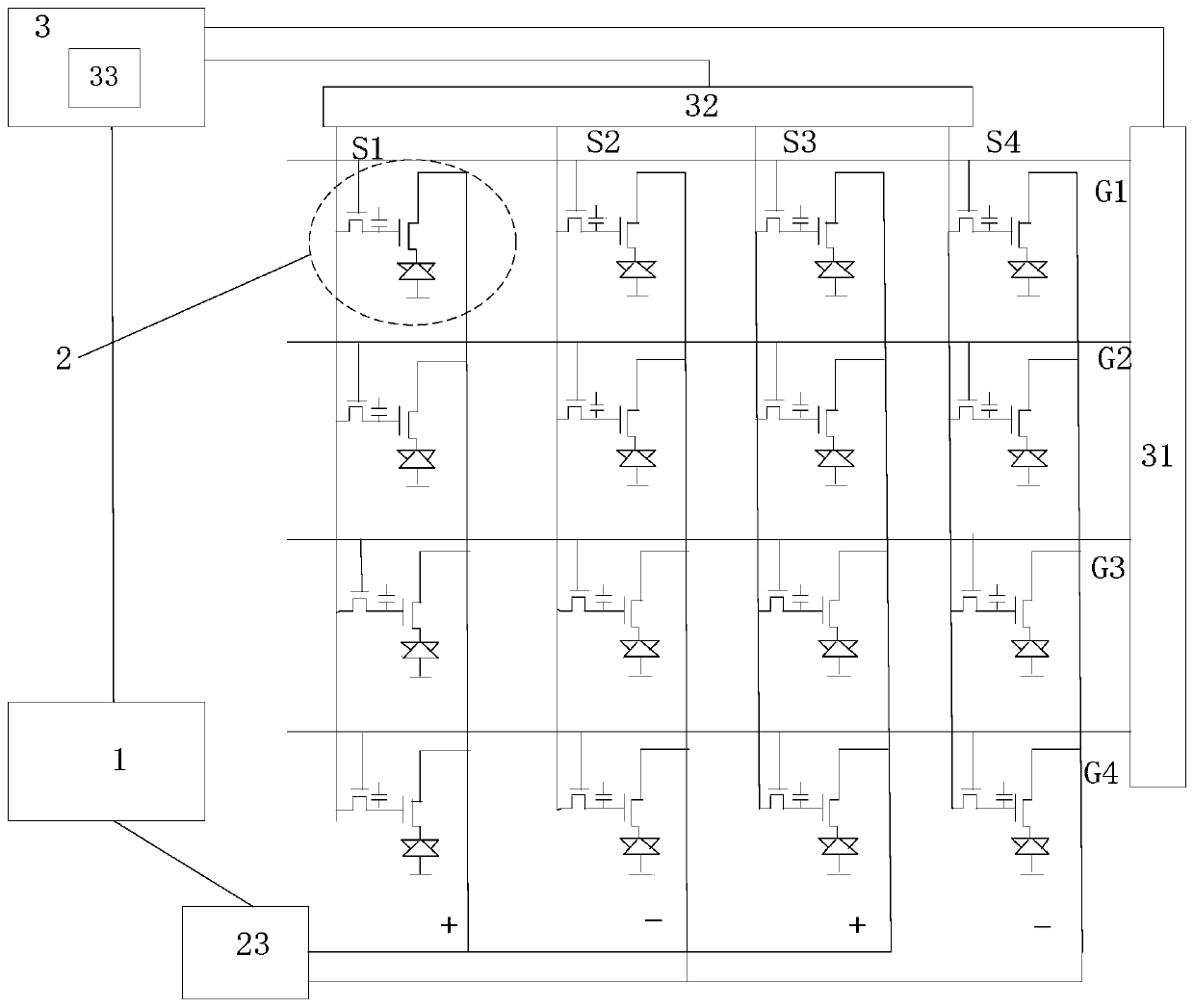
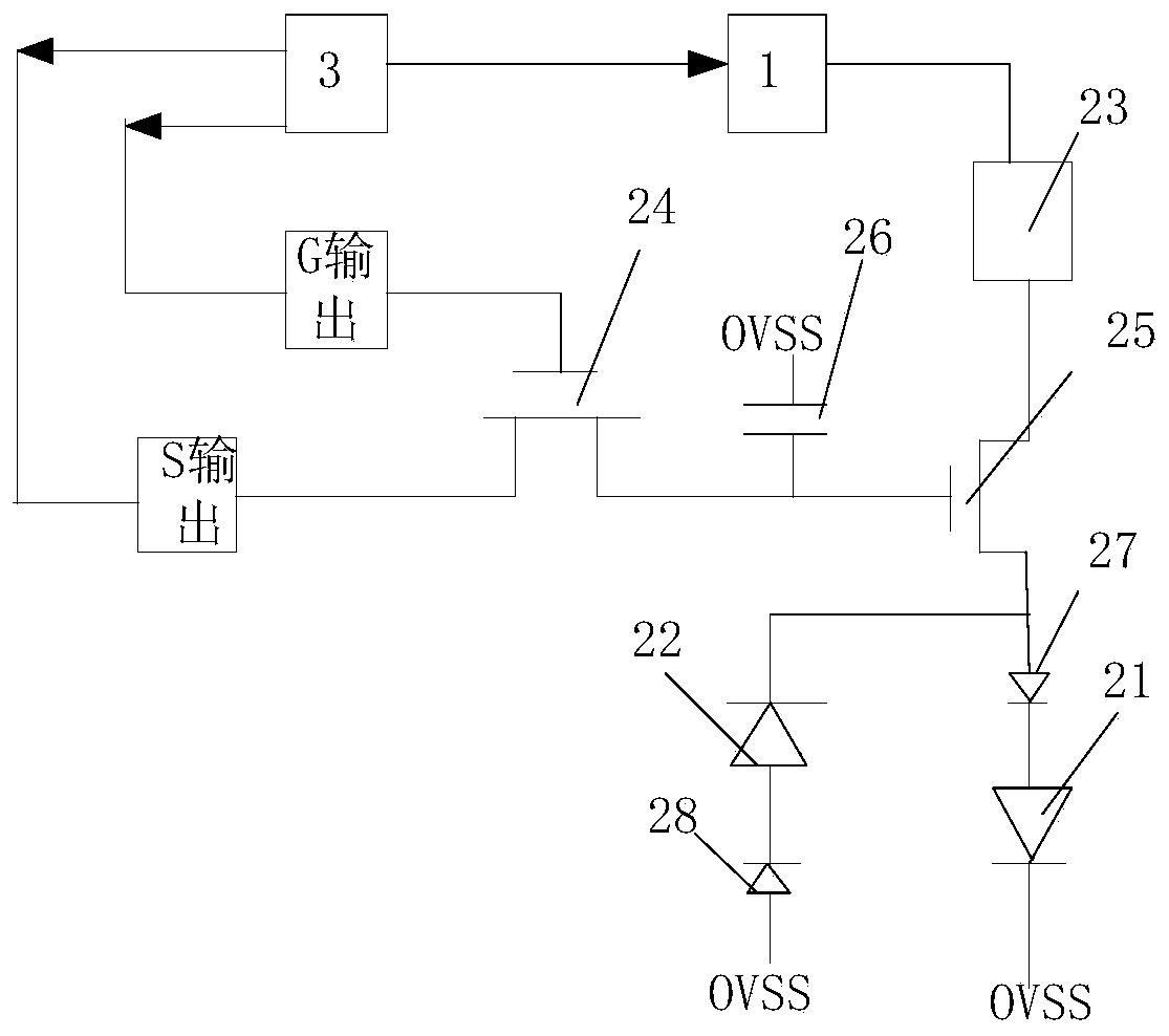
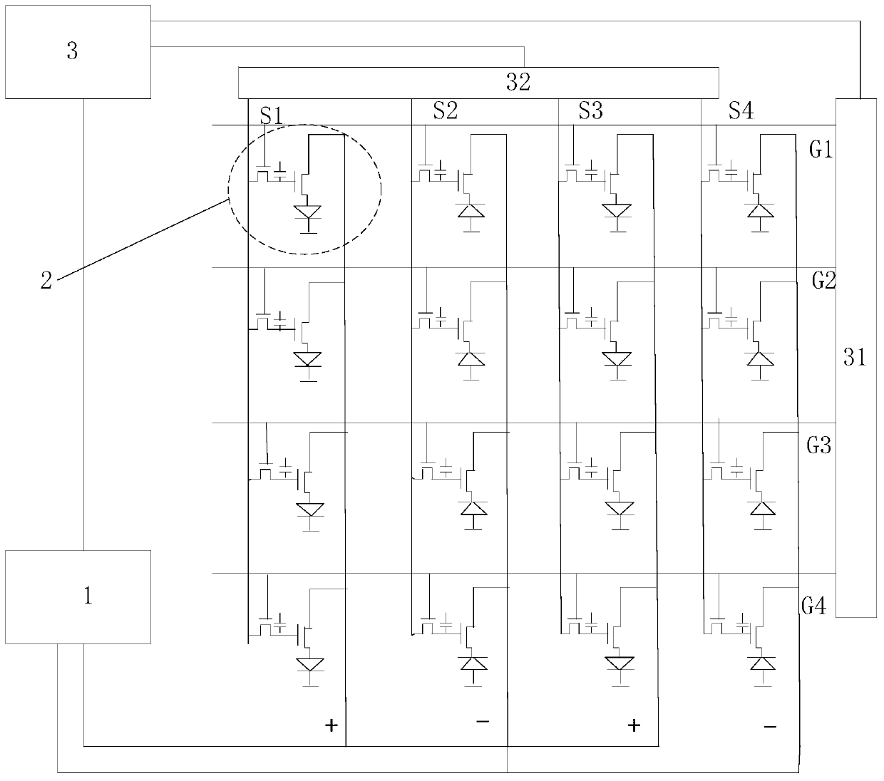
[0049]A display drive circuit provided by the present invention includes a power supply module 1, a light-emitting component 2 and a control module 3, the power supply module 1 provides positive and negative driving voltages; a plurality of light-emitting components 2 are arranged in a matrix, and a plurality of the The light-emitting components 2 are all electrically connected to the power module 1, and the driving voltage polarity of the light-emitting components 2 in some rows / columns of the multiple light-emitting components 2 is opposite to that of the remaining rows / columns of the light-emitting components 2; The control module 3 is electrically connected to the power module 1, and is used to control the power module 1 to provide positive / negative driving voltages for the light-emitting components 2 corresponding to the row / column; the control module 3 receives image signals, and the control module 3 The module 3 is electrically connected to a plurality of the light-emitt...

Embodiment 2

[0104] Furthermore, an embodiment of the present invention proposes a display panel. In a specific implementation, the display panel includes any one of the display driving circuits described in Embodiment 1.

Embodiment 3

[0106] Furthermore, one embodiment of the present invention provides an electronic device, and in a specific implementation, the electronic device includes the display panel described in Embodiment 2.


PUM


Abstract

The invention discloses a display driving circuit, and relates to the technical field of display equipment. According to the main technical scheme, the display driving circuit comprises a power module, light-emitting assemblies and a control module, and the power module provides positive and negative driving voltages; the plurality of light-emitting assemblies are arranged in a matrix manner, theplurality of light-emitting assemblies are all electrically connected with the power supply module, and the driving voltage polarities of the light-emitting assemblies in adjacent rows/adjacent columns are opposite; the control module is electrically connected with the power module and is used for controlling the power module to provide a positive/negative driving voltage for the light-emitting assemblies in the corresponding rows/columns; and the control module receives an image signal, is electrically connected with the plurality of light-emitting assemblies and is used for providing an equal gate voltage/source voltage for the light-emitting assemblies in the same row/column according to the image signal.

Description

technical field [0001] The present invention relates to the technical field of display equipment, in particular to a display driving circuit, a display panel and electronic equipment. Background technique [0002] With the progress of the times, organic light-emitting diode (Organic Light-Emitting Diode, OLED) display technology is more and more favored by people. [0003] Existing OLED display panels are all driven by positive pressure. Full positive voltage drive means that the drive circuits in the display panel are all positive voltage and positive current in the same direction, which produces coupling effects in the panel and external electromagnetic interference, and then Electromagnetic interference will be generated on the touch panel on the upper layer of the display panel, which may cause noise, decrease in signal-to-noise ratio, and even poor touch control. Contents of the invention [0004] In view of this, the embodiments of the present invention provide a di...

Claims


Application Information

Patent Timeline
Patent Type & Authority Applications(China)
IPC IPC(8): G09G3/3208
CPCG09G3/3208
Inventor 李鹏涛于洁尹大根马青韩锐张阳阳
Owner BOE TECH GRP CO LTD
Why Eureka
Try Eureka