Direct-current solid-state circuit breaker
A solid-state circuit breaker and DC bus technology, applied in emergency protection circuit devices, electrical components, etc., can solve the problems of judging the fault state of faulty circuits, unable to detect stable current and voltage signals, etc.
- Summary
- Abstract
- Description
- Claims
- Application Information
AI Technical Summary
Problems solved by technology
Method used
Image
Examples
Embodiment approach 1
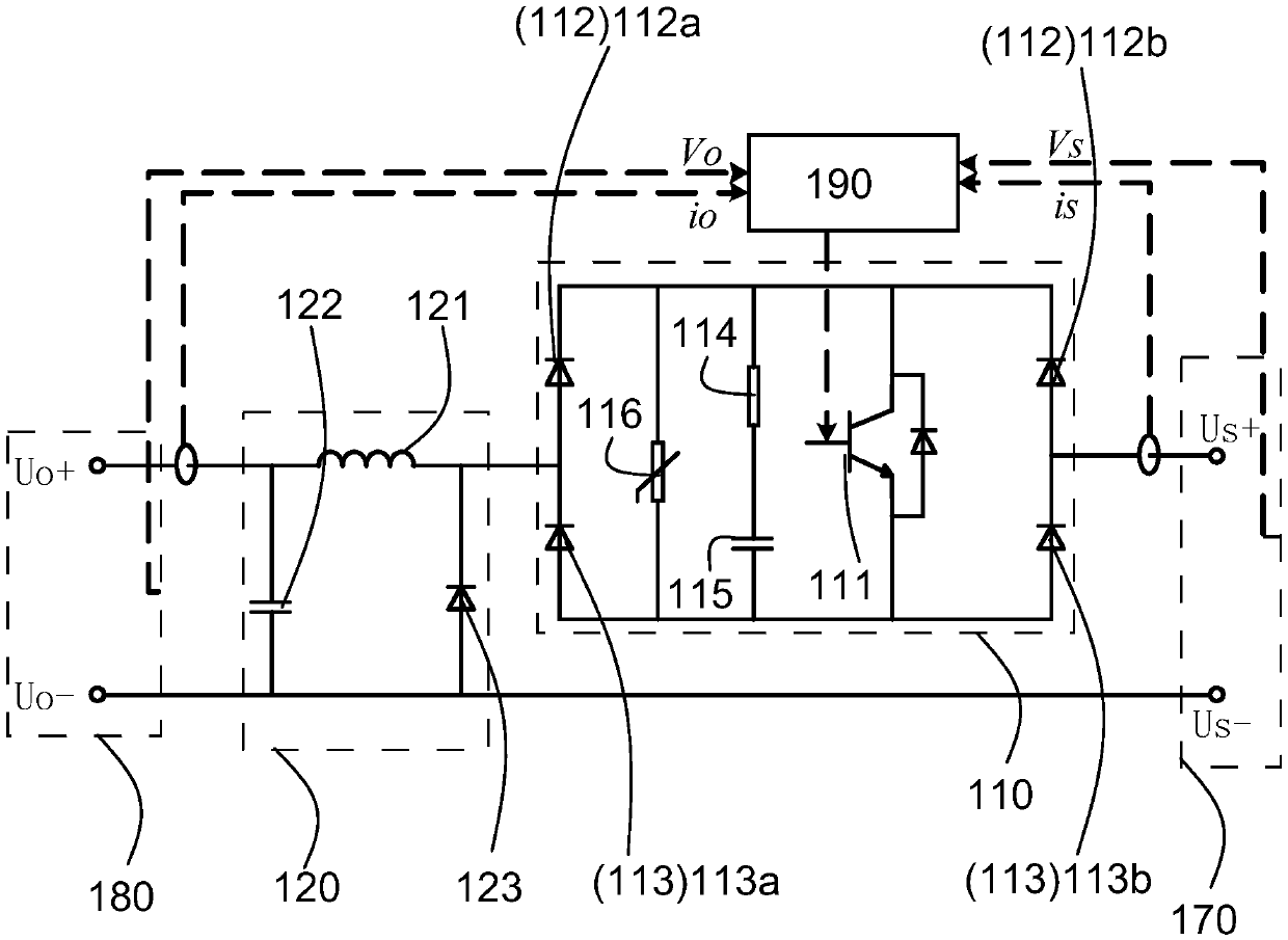
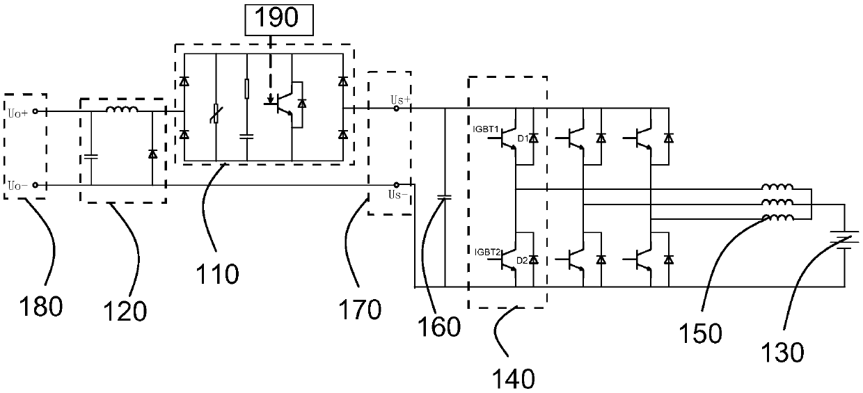
[0046] Figures 1 to 2 A preferred embodiment according to the invention is shown. The DC solid-state circuit breaker of this embodiment is used to connect the energy source and the DC bus of the DC power grid, and to control the on-off of the circuit between the energy source and the DC bus. The energy source of this embodiment is the battery pack 130 . The DC solid state circuit breaker includes an energy source terminal 170 for connecting to an energy source, and a DC bus terminal 180 for connecting to a DC bus. The positive pole of the energy source terminal 170 is used to connect with the positive pole of the energy source. The negative pole of the energy source terminal 170 is used to connect with the negative pole of the energy source. The positive pole of the DC bus terminal 180 is used to connect with the positive pole of the DC bus. The negative pole of the DC bus terminal 180 is used to connect with the negative pole of the DC bus. This achieves electrical isol...
Embodiment approach 2
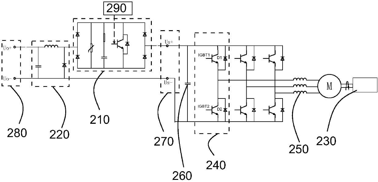
[0070] image 3 Another preferred embodiment according to the invention is shown. The switching circuit 210 , the freewheeling circuit 220 , the filter capacitor 260 and the energy source terminal 270 in the second embodiment are the same as the switching circuit 110 , the freewheeling circuit 120 , the filter capacitor 160 and the energy source terminal 170 in the first embodiment. The difference between Embodiment 2 and Embodiment 1 is that the energy source is a generator set 230 . The low-voltage side of the buck-boost circuit 240 is connected to the generator set 230 through a filter inductor 250 and a filter (not shown in the figure). The emitter of the IGBT2 of each bidirectional Buck-Boost circuit is only connected to the negative pole of the DC bus terminal 280 , but not connected to the generator set 230 . Moreover, the controller 290 controls the buck-boost circuit 240 to perform rectification, so as to convert the alternating current generated by the generator se...
Embodiment approach 3
[0072] The invention also provides an implementation manner of a direct current power grid. The DC power grid in this embodiment includes a DC bus-tie solid-state circuit breaker and the aforementioned DC solid-state circuit breaker. The positive and negative poles of the DC bus terminal of the DC solid state circuit breaker correspond to the positive and negative poles of the DC bus connected to the DC grid. The DC bus-tie solid-state circuit breaker is similar to the DC solid-state circuit breaker with quick cut-off function in the prior art, and will not be repeated here.
[0073] Such as Figure 5 The DC grid shown provides electrical energy to the ship's DC electric propulsion system. Specifically, in the DC power grid, the energy source 1 is connected to the left busbar of the distribution network 1 through the DC solid state circuit breaker 1, and the energy source 2 is connected to the right busbar of the distribution network 1 through the DC solid state circuit brea...
PUM
 Abstract
Description
Claims
Application Information
 - R&D
- Intellectual Property
- Life Sciences
- Materials
- Tech Scout
- Unparalleled Data Quality
- Higher Quality Content
- 60% Fewer Hallucinations
Browse by: Latest US Patents, China's latest patents, Technical Efficacy Thesaurus, Application Domain, Technology Topic, Popular Technical Reports.
© 2025 PatSnap. All rights reserved.Legal|Privacy policy|Modern Slavery Act Transparency Statement|Sitemap|About US| Contact US: help@patsnap.com


