Glass polishing equipment

A glass and equipment technology, applied in the field of glass polishing equipment, can solve the problems of difficult and uniform polishing of glass

Inactive Publication Date: 2020-06-02
安徽超文玻璃科技有限公司
View PDF15 Cites 2 Cited by
  • Summary
  • Abstract
  • Description
  • Claims
  • Application Information

AI Technical Summary

Problems solved by technology

[0005] The technical problem to be solved by the present invention is to provide a polishing equipment for glass to solve the problem that the glass is difficult to polish uniformly

Method used


Image

  • Glass polishing equipment
  • Glass polishing equipment
  • Glass polishing equipment

Examples


Embodiment 1

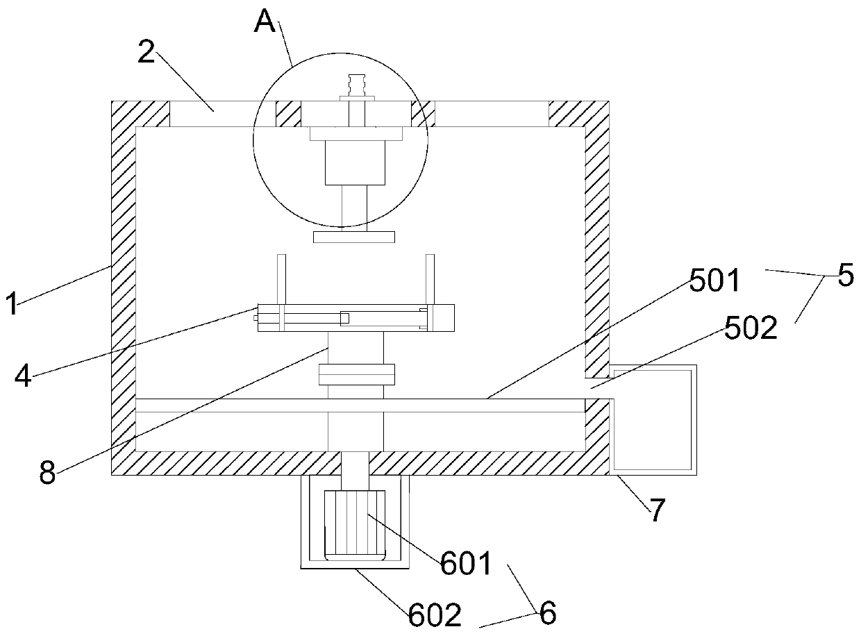
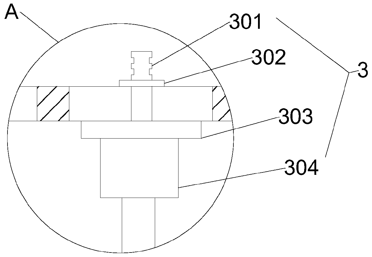
[0033] figure 1 It is a schematic structural diagram of a polishing device for glass provided in Embodiment 1 of the present invention; figure 2 for figure 1 The schematic diagram of the enlarged structure of A; such as Figure 1-Figure 2 , a glass polishing device, comprising a housing 1, a see-through window 2, a polishing mechanism 3, a fixing mechanism 4, a rotating mechanism 5, a driving mechanism 6, a dust collection box 7 and a rotating rod 8, the top of the housing 1 A polishing mechanism 3 is arranged in the middle, and the top of the housing 1 is symmetrically fixed on both sides of the polishing mechanism 3 with see-through windows 2 for observation, and the polishing mechanism 3 is provided with a fixing mechanism 4 directly below the inside of the housing 1. The bottom of the fixing mechanism 4 is fixedly connected with the rotating mechanism 5 through the rotating rod 8, and the lower end of the rotating rod 8 passes through the rotating mechanism 5 and is fix...

Embodiment 2

[0046] Such as Figure 6 , Figure 6 A schematic structural diagram of a polishing device for glass provided by Embodiment 2 of the present invention. The difference between Embodiment 2 and Embodiment 1 is that the drive mechanism 6 is replaced by a fan 9. Others are the same as Embodiment 1. This embodiment Among them, the bolts of the fan 9 are arranged on the top of the fixing mechanism 4 and the left side wall of the housing 1, so that under the action of the fan 9, dust etc. will be blown into the dust collection box 7 by the wind.

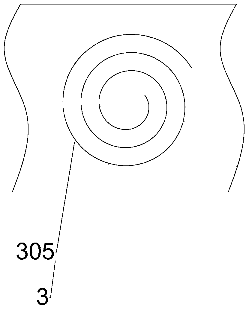
[0047] Working principle: adjust the height in advance, then manually hold the upper end of the connecting rod 301, and then move the connecting rod 301 along the spiral track 305. At this time, the polishing machine 304 will be polished under the drive of the connecting rod 301. 4051, drives the first rotating rod 4052 to rotate, and the external thread 4053 cooperates with the internal thread. When the first rotating rod 4052 rotates cloc...


PUM


Abstract

The invention relates to glass polishing equipment. The glass polishing equipment comprises a shell, a polishing mechanism, a fixing mechanism, a rotating mechanism, a driving mechanism, a dust collecting box and a rotating rod, wherein the polishing mechanism is arranged in the middle of the top of the shell, and the fixing mechanism is arranged at the position, right under the interior of the shell, of the polishing mechanism; the lower portion of the fixing mechanism is fixedly connected with the rotating mechanism through the rotating rod, the lower end of the rotating rod penetrates through the rotating mechanism and is fixedly connected with an output shaft of the driving mechanism, and the fixedly-connected dust collecting box is further arranged on the side wall of the shell; and aspiral rail is formed in the middle of the top of the shell, and the polishing mechanism penetrates through the spiral rail to extend into the interior of the shell and slides along the track of thespiral rail. According to the glass polishing equipment, the polishing mechanism can move along the spiral rail, and the spiral rail can cover all parts of a glass finished product after the polishingmechanism moves along the spiral rail so that uniform polishing can be realized.

Description

technical field [0001] The invention relates to the technical field of glass processing, in particular to a polishing device for glass. Background technique [0002] With the continuous development and progress of society, glass products are becoming more and more important. Glass is an amorphous inorganic non-metallic material. It is generally made of various inorganic minerals (such as quartz sand, borax, boric acid, barite, barium carbonate, limestone, Feldspar, soda ash, etc.) are the main raw materials, and a small amount of auxiliary raw materials are added. Glass is widely used in buildings to transmit light and wind. [0003] Most of the existing glass products need to be polished, but when polishing, it is difficult to ensure that every part of the glass product is polished at the same time and with the same intensity, that is, it is difficult to achieve uniform polishing, which leads to the production of glass products. Quality product. [0004] The utility mode...

Claims


Application Information

Patent Timeline
IPC IPC(8): B24B7/04B24B7/24B24B41/06B24B47/00B24B47/16B24B55/06B24B55/12
CPCB24B7/04B24B7/245B24B7/247B24B41/06B24B47/00B24B47/16B24B55/06B24B55/12
Inventor 谭超文谭秀兵曹敏谈岫学
Owner 安徽超文玻璃科技有限公司
Why Eureka
Try Eureka