
Gas leakage monitoring system

A gas leakage and monitoring system technology, applied in the direction of color/spectral characteristic measurement, etc., can solve the problem of high false negative rate, achieve the effect of low false positive rate, improve sensitivity, and avoid electromagnetic interference

Pending Publication Date: 2020-06-02
BC P INC CHINA NAT PETROLEUM CORP +2
View PDF0 Cites 0 Cited by
  • Summary
  • Abstract
  • Description
  • Claims
  • Application Information

AI Technical Summary

Problems solved by technology

[0005] The existing technology can only monitor when a large amount of gas leakage occurs in the pressure gas pipelines and containers in the area to be monitored, which has the characteristics of high false alarm rate

Method used


Image

  • Gas leakage monitoring system
  • Gas leakage monitoring system
  • Gas leakage monitoring system

Examples


Embodiment Construction

[0054] In order to make the objectives, technical solutions and advantages of the present invention clearer, the embodiments of the present invention will be further described in detail below with reference to the accompanying drawings.

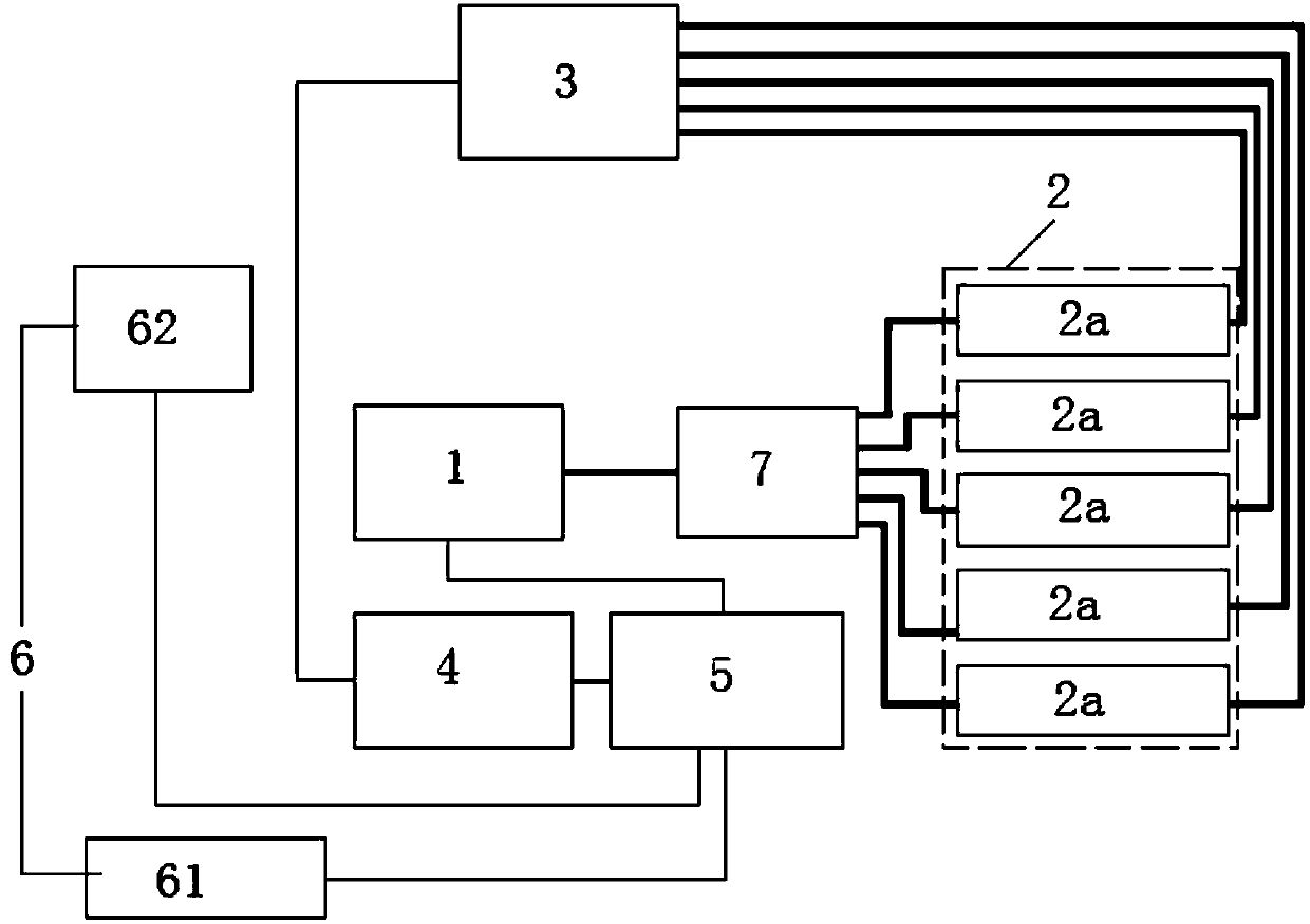
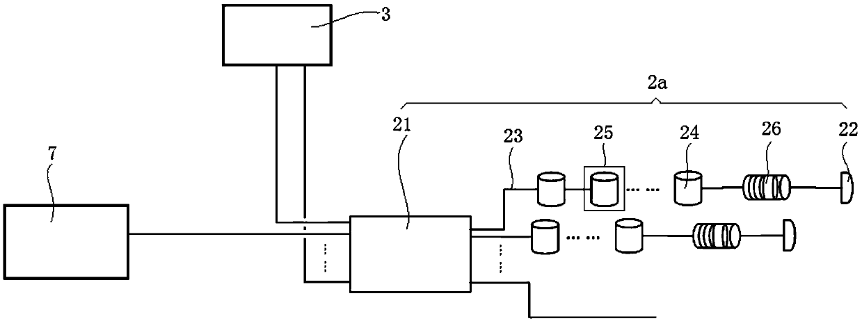
[0055] The embodiment of the present invention provides a gas leakage monitoring system, such as the attached figure 1 As shown, the gas leakage monitoring system includes: a laser 1, an optical fiber sensor assembly 2, a photoelectric conversion module 3 connected in sequence by optical fibers; and an electrical signal acquisition module 4, an electrical signal processing module 5, and an alarm signal sequentially connected by wires The output module 6, the electrical signal acquisition module 4 is connected to the photoelectric conversion module 3 through wires, and the electrical signal processing module 5 is connected to the laser 1 through wires; the laser 1 is used to emit laser light to the optical fiber sensor assembly 2; When there i...


PUM

PropertyMeasurementUnit
thicknessaaaaaaaaaa

Abstract

The invention, which belongs to the field of gas leakage monitoring, discloses a gas leakage monitoring system comprising a laser, an optical fiber sensor assembly and a photoelectric conversion module which are connected in sequence, an electric signal acquisition module, an electric signal processing module and an alarm signal output module that are connected in sequence. The electric signal acquisition module is connected with the photoelectric conversion module, and the electric signal processing module is connected with the laser; the laser is used for emitting laser to an optical fiber sensor; the optical fiber sensor is used for enabling the laser to generate a first interference light wave signal and enabling the laser to generate a second interference light wave signal by utilizing ultrasonic waves generated by gas leakage; the photoelectric conversion module is used for converting the first interference light wave signal and the second interference light wave signal into a first electric signal and a second electric signal which are transmitted to the electric signal processing module through the electric signal acquisition module; and the electric signal processing module is used for judging whether gas leakage occurs in the to-be-monitored area and outputting a judgment result through the alarm signal output module.

Description

technical field [0001] The invention relates to the field of gas leakage monitoring, in particular to a gas leakage monitoring system. Background technique [0002] For pressure gas pipelines and containers on the ground, such as pipelines and containers in natural gas pipeline stations, shale gas production well platforms, etc., they are easily affected by factors such as welding construction quality, corrosion, and pipe fitting quality. Natural gas) leakage, which will not only lead to economic losses, but also prone to safety accidents. Therefore, it is necessary to timely and effectively monitor whether gas leakage occurs in the above-mentioned areas. [0003] In the prior art, flow pressure gauges are generally used, and methods such as pressure gradient method and cross-correlation method are used to judge whether gas leakage occurs in the pressure gas pipelines and containers in the area to be monitored. [0004] The inventor found that the prior art has at least th...

Claims


Application Information

Patent Timeline
Patent Type & Authority Applications(China)
IPC IPC(8): G01N21/39
CPCG01N21/39
Inventor 王飞赵岩郭戈赵锋厉宇侯志相李锐李维李刚杨文明陈静王文星
Owner BC P INC CHINA NAT PETROLEUM CORP
Learn More