
Winding equipment of high-frequency transformer coil

A high-frequency transformer and coil technology, applied in the field of transformers, can solve the problems of reduced work efficiency, single function, loose coil arrangement, etc., and achieve the effect of avoiding uneven winding, ensuring compactness, and ensuring uniformity

Active Publication Date: 2020-06-02
FUZHOU CITY SHUANGLING MAGNETIC MATERIALS
View PDF8 Cites 3 Cited by
  • Summary
  • Abstract
  • Description
  • Claims
  • Application Information

AI Technical Summary

Problems solved by technology

In the manufacturing process of transformers, the winding of coils is also very important. The traditional coil winding machine has a single function, only winding the electromagnetic wire through simple rotation, and the degree of automation is low. In the process of winding, the coil arrangement is relatively loose, which affects the use effect of the transformer, and the cutting cannot be completed automatically during the winding process, and manual operation is required, thereby reducing work efficiency, and quantitative winding cannot be guaranteed during the manual cutting process , the uniformity between products cannot be guaranteed
[0004] In order to solve the above problems, the inventor proposed a high-frequency transformer coil winding equipment, which has the advantages of neat winding and automatic cutting, which solves the problem of single function and low degree of automation of traditional winding equipment, and ensures When using this device to operate, it is more intelligent and has a higher degree of automation, which improves work efficiency

Method used


Image

  • Winding equipment of high-frequency transformer coil
  • Winding equipment of high-frequency transformer coil
  • Winding equipment of high-frequency transformer coil

Examples


Embodiment Construction

[0028] The following will clearly and completely describe the technical solutions in the embodiments of the present invention with reference to the accompanying drawings in the embodiments of the present invention. Obviously, the described embodiments are only some, not all, embodiments of the present invention. Based on the embodiments of the present invention, all other embodiments obtained by persons of ordinary skill in the art without making creative efforts belong to the protection scope of the present invention.

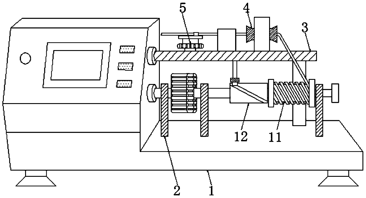
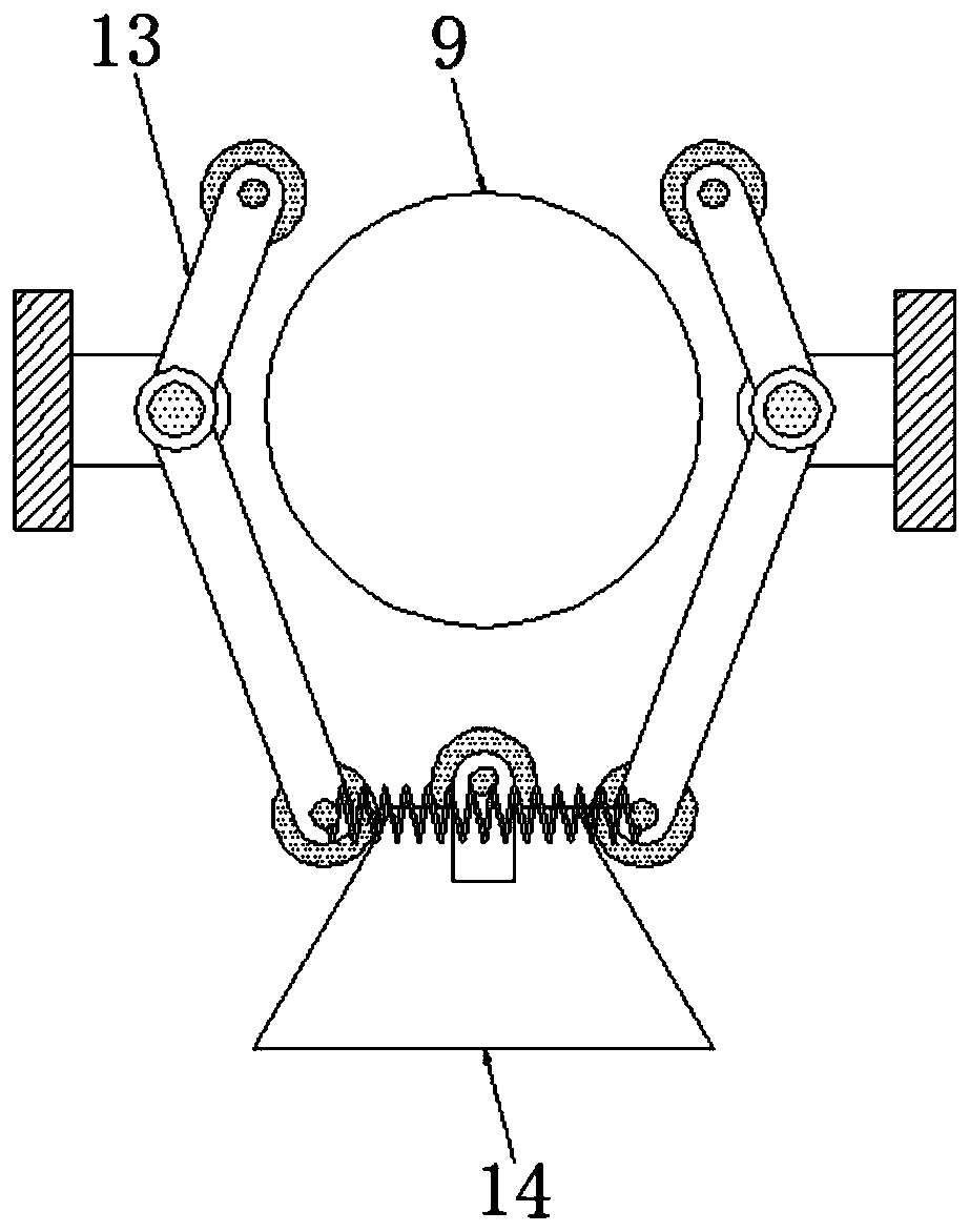
[0029] see Figure 1-9 , a high-frequency transformer coil winding equipment, including a base 1, a support rod 2 is fixedly connected above the base 1 to support the first rotating shaft 9, a horizontal plate 3 is fixedly connected above the support rod 2, and the horizontal plate is used to 3 Support the gear 5, and the upper part of the horizontal plate 3 is fixedly connected with the limit circle 4. By passing the electromagnetic wire through the limit cir...


PUM


Abstract

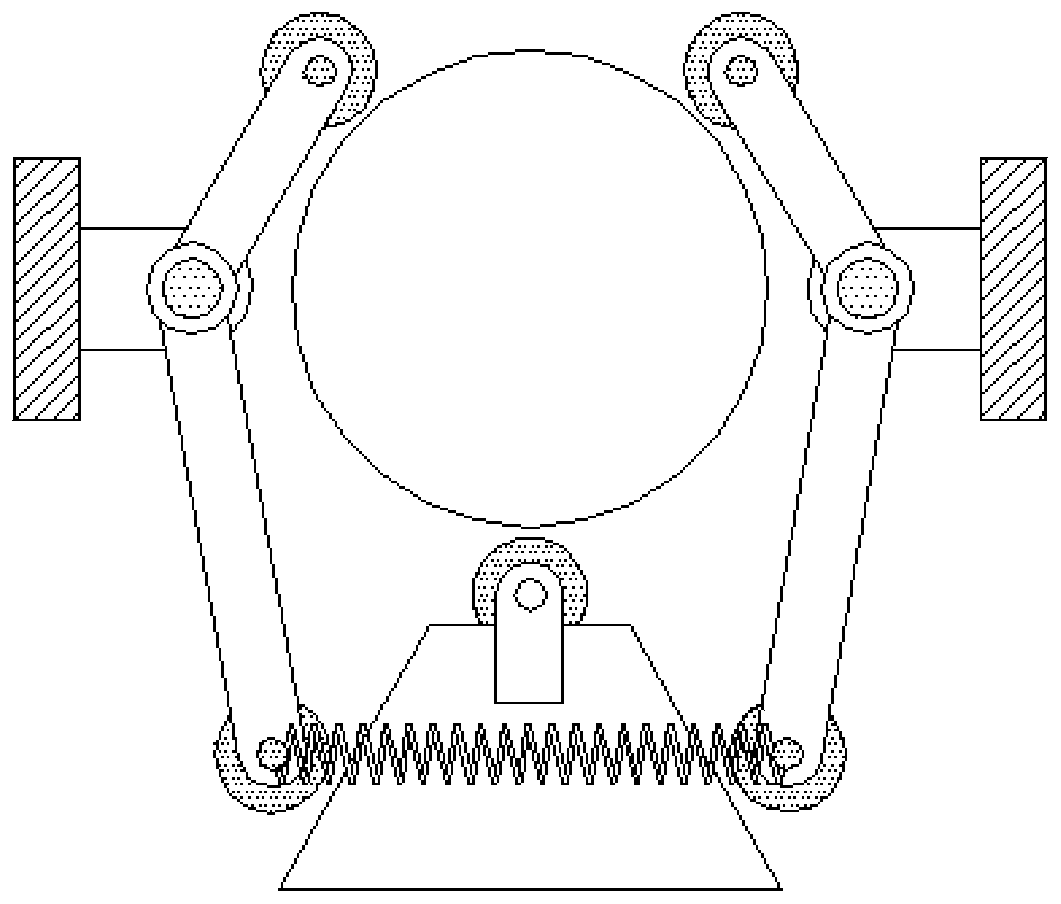
The invention relates to the technical field of transformers, and discloses winding equipment of a high-frequency transformer coil. The winding equipment comprises a base, wherein a supporting rod isfixedly connected to the upper part of the base, a first rotating shaft is supported, a transverse plate is fixedly connected above the supporting rod, the transverse plate is used for supporting a gear, a limiting ring is fixedly connected above the transverse plate, an electromagnetic wire is quantitatively cut through regular operation by means of the cooperative use of the gear, a turntable, apush rod and a cutting blade, so that quantitative winding is carried out, the uniformity of the transformer coil is ensured; a first rotating shaft, a second rotating shaft, a reel and a sleeve rodare used in a matched manner to enable a winding wheel to rotate and move left and right at the same time, so that it is guaranteed that coil is evenly distributed on the surface of the winding wheel,and uneven winding is avoided; and through cooperative use of a limiting rod and a trapezoidal plate, the winding wheel stops rotating while the winding is finished, so that the wound coil is prevented from loosening, and the compactness of the coil is guaranteed.

Description

technical field [0001] The invention relates to the technical field of transformers, in particular to winding equipment for high-frequency transformer coils. Background technique [0002] With the sustained, healthy and rapid development of China's economy, the demand for electricity continues to grow rapidly. As the key electrical equipment for power transmission, the market demand for transformers has also maintained a steady growth. Therefore, there is a very broad market for the manufacture of transformers. [0003] A transformer is a device that transforms AC voltage, alternating current, and impedance. When an AC current passes through the primary coil, an AC magnetic flux is generated in the iron core (or magnetic core), which induces a voltage (or current) in the secondary coil. , The transformer consists of an iron core (or magnetic core) and a coil. The coil has two or more windings. The winding connected to the power supply is called the primary coil, and the rema...

Claims


Application Information

Patent Timeline
Patent Type & Authority Applications(China)
IPC IPC(8): H01F41/082H01F41/098
CPCH01F41/082H01F41/098
Inventor 吴世伟
Owner FUZHOU CITY SHUANGLING MAGNETIC MATERIALS
Learn More