Multi-harmonic signal undersampling method based on multi-channel time delay

A harmonic signal and multi-channel technology, applied in the field of signal processing, can solve problems such as image frequency aliasing and frequency aliasing, and achieve the effect of improving signal-to-noise ratio, reducing difficulty, and reducing the number of sampling points

Active Publication Date: 2020-06-02
HARBIN INST OF TECH
View PDF4 Cites 5 Cited by
  • Summary
  • Abstract
  • Description
  • Claims
  • Application Information

AI Technical Summary

Problems solved by technology

[0005] The present invention proposes a multi-harmonic signal under-sampling method based on multi-channel delay to so...

Method used


Image

  • Multi-harmonic signal undersampling method based on multi-channel time delay
  • Multi-harmonic signal undersampling method based on multi-channel time delay
  • Multi-harmonic signal undersampling method based on multi-channel time delay

Examples


Embodiment 1

[0042] A multi-harmonic signal under-sampling method based on multi-channel delay, the sampling method is specifically: composed of N'≥2 adjacent channels and parallel sampling channels with a time delay τ, the sampling of N' channels The rate is the same, there is a relative delay in the sampling time of N' channels;

[0043] Step 1: Initialize;

[0044] Step 2: After the multi-harmonic signal x(t) is shunted, it enters N' parallel sampling channels respectively, and each sampling channel performs uniform low-speed sampling on the signal at the same sampling rate, and the number of sampling points of each channel is N;

[0045] Step 3: Combine the sampling data of each sampling channel to construct the autocorrelation matrix R xx , and use the ESPRIT method to estimate the sampling signal parameter c of each channel m and a set of frequency parameters

[0046] Step 4: Estimated parameter c via m , the sampling delay τ of each channel, and use the ESPRIT method to estimate...

Embodiment 2

[0068] noise-free experiment

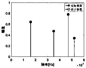
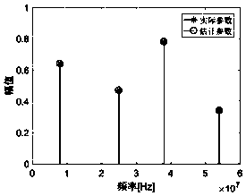
[0069] Set the number of frequency components of the signal to be tested to K=4, the maximum signal frequency is set to 60MHz, and the sampling rate of each delay channel is f s =30MHz, the sampling delay of each channel When there is no signal image frequency aliasing, the number of sampling channels is set to N'=2, and the number of sampling points per channel is N=12. figure 2 shows the signal amplitude a k and the frequency parameter f k reconstruction effect. When there is signal image frequency aliasing, the number of sampling channels is set to N'=16, and the number of sampling points per channel is N=16. image 3 shows the signal amplitude a k and the frequency parameter f k reconstruction effect. It can be seen that the sampling structure and method can reconstruct the amplitude parameter and frequency parameter of the signal without error in both cases of no signal image frequency aliasing and signal image frequency aliasing. ...

Embodiment 3

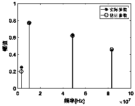
[0071] noise experiment

[0072] Set the number of frequency components of the signal to be tested to K=4, the maximum signal frequency is set to 100MHz and there is no signal image frequency aliasing, and the sampling rate of each delay channel is f s =14MHz, the sampling delay of each channel The number of sampling channels is set to N'=4, the number of sampling points per channel is N=50, and the signal-to-noise ratio is 10dB. Figure 4 shows the signal amplitude a k and the frequency parameter f k reconstruction effect. Figure 5 The reconstruction effect of the signal time domain waveform is shown; the experimental results show that in the case of a SNR of 10dB, the sampling structure and method can well estimate the signal parameters and recover the signal time domain waveform.


PUM


Abstract

The invention discloses a multi-harmonic signal undersampling method based on multi-channel time delay. The method comprises the following steps: 1, performing initialization; 2, enabling a multi-harmonic signal x (t) to enter N' parallel sampling channels after being shunted, wherein the number of sampling points of each channel is N; 3, constructing an autocorrelation matrix Rxx by combining thesampling data of each sampling channel, and estimating a sampling signal parameter cm of each channel and a group of frequency parameters by using an ESPRIT method; 4, estimating the signal amplitudeam and another group of frequency parameters through the estimated parameter cm, sampling time delay tau of each channel and a ESPRIT method;; and 5, reconstructing 2K frequency parameters through the estimated two groups of minimum frequencies and a closed-form robust Chinese remainder theorem, and screening out correct K frequency parameters through sampling rate parameters. The method is usedfor solving the problems of frequency aliasing and mirror image frequency aliasing occurring in real number domain multi-harmonic signal undersampling.

Description

technical field [0001] The invention belongs to the technical field of signal processing; in particular, it relates to a multi-harmonic signal under-sampling method based on multi-channel delay. Background technique [0002] Multi-harmonic signals are the superposition of multiple sinusoidal signals, and are widely used in communication, radar, medical equipment, frequency domain measurement and other fields. According to the Nyquist (Nyqiust) sampling theorem, in order to restore the analog signal without distortion from discrete sampling samples, the sampling rate must be greater than or equal to twice the signal bandwidth. With the development of modern information technology, the bandwidth of multi-harmonic signals is gradually increasing, and the pressure on sampling equipment is also increasing. Therefore, the Nyquist sampling theorem has gradually become a bottleneck in the design of multi-harmonic signal sampling systems, restricting the development of signal proces...

Claims


Application Information

Patent Timeline
IPC IPC(8): H03M7/30G01R23/16
CPCH03M7/30G01R23/16G06F7/729G06F17/141H03M1/1285G06F17/16H04L27/2601
Inventor 付宁尉志良闫振龙乔立岩彭喜元
Owner HARBIN INST OF TECH
Why Eureka
Try Eureka