
Denitration system for flue gas denitration by utilizing ozone and turbulent ball tower

A turbulent ball tower and ozone technology, applied in the field of flue gas denitrification, can solve the problems of increasing ozone dosage, increasing cost, and poor effect

Pending Publication Date: 2020-06-05
SHANDONG NORMAL UNIV
View PDF7 Cites 1 Cited by
  • Summary
  • Abstract
  • Description
  • Claims
  • Application Information

AI Technical Summary

Problems solved by technology

More critically, the actual conditions of the flue gas, such as higher temperature (about 100--300 ℃), lower pressure (about kilopascal level, even negative pressure), low nitric oxide Concentration (approximately dozens - 500mg / m 3 ), faster flow rate (about 1--10m / s), etc. will greatly affect the existence of ozone and its oxidation effect on NO
In actual production, the reason why the ozone oxidation method has not been popularized and applied on a large scale is because its effect is not good.
In order to improve the oxidation effect, in the prior art, the dosage of ozone is increased, which will lead to increased costs and cannot be popularized and applied.

Method used


Image

  • Denitration system for flue gas denitration by utilizing ozone and turbulent ball tower
  • Denitration system for flue gas denitration by utilizing ozone and turbulent ball tower
  • Denitration system for flue gas denitration by utilizing ozone and turbulent ball tower

Examples


Embodiment 1

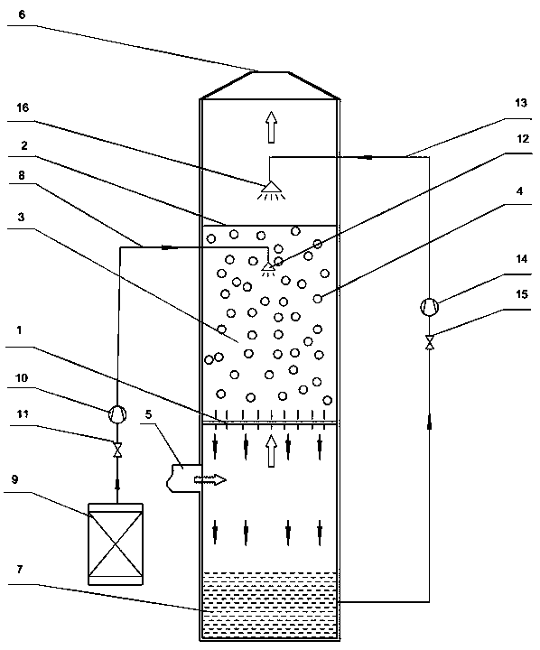
[0075] combined with figure 1 , the present invention is described:

[0076] The turbulent ball tower is a cylinder with a diameter of 0.8m, a tower height of 5m, a wall thickness of 8mm, and is made of 304L stainless steel. The support plate 1 is installed at a position 2.5 meters away from the bottom of the tower shell. The support plate 1 is a circular grid plate structure with a gap spacing of 15mm, and the material is 304 stainless steel. There is a retaining net 2 at 1.5m above the supporting plate 1, and the hole diameter of the retaining net 2 is 20mm. The space between the supporting plate 1 and the retaining net 2 is the turbulent ball area 3, and the turbulent ball 4 is placed in the turbulent ball area 3, and the turbulent ball 4 is a 34mm hollow PE ball, and the height of the turbulent ball layer is about 0.4m when it is empty. The flue gas inlet 5 is set at a position 1.5m away from the bottom of the turbulent ball tower, the flue gas outlet 6 is set at the to...

Embodiment 2

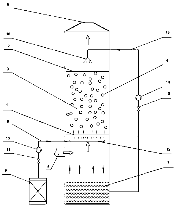
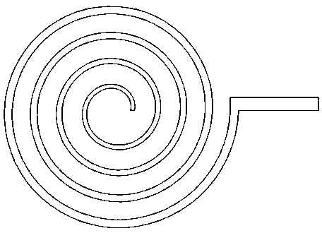
[0082] combined with figure 2 And attached image 3 , the present invention is described:

[0083] The turbulent ball tower is a cylinder with a diameter of 0.8m, a tower height of 5m, a wall thickness of 8mm, and is made of 304L stainless steel. The support plate 1 is installed at a position 2.5 meters away from the bottom of the tower shell. The support plate 1 is a circular grid plate structure with a gap spacing of 15mm, and the material is 304 stainless steel. There is a retaining net 2 at 1.5m above the supporting plate 1, and the hole diameter of the retaining net 2 is 20mm. The space between the supporting plate 1 and the retaining net 2 is the turbulent ball area 3, and the turbulent ball 4 is placed in the turbulent ball area 3, and the turbulent ball 4 is a 34mm hollow PE ball, and the height of the turbulent ball layer is about 0.4m when it is empty. The flue gas inlet 5 is set at a position 1.5m away from the bottom of the turbulent ball tower, the flue gas out...


PUM


Abstract

The invention discloses a denitration system for flue gas denitration by utilizing ozone and a turbulent ball tower. The system comprises a turbulent ball tower, an ozone supply system and a soluble alkali liquor supply system, the soluble alkali liquor supply system conveys soluble alkali liquor into a turbulent ball area of the turbulent ball tower through a liquid inlet pipe; wherein a plurality of turbulent balls are arranged in the turbulent ball area, an ozone distributor is arranged in the turbulent ball tower, the position height of the ozone distributor is below the height of the turbulent ball area, the ozone supply system conveys ozone to the ozone distributor through an air inlet pipe, flue gas enters the turbulent ball area from the lower part, and the flue gas in the turbulent ball area is mutually mixed, reacted and subjected to mass transfer with soluble alkali liquor and ozone. The system is used for ozone denitration, and has great economic benefits and social benefits.

Description

technical field [0001] The invention relates to the technical field of flue gas denitrification, in particular to a destocking system for flue gas denitrification by using ozone and a turbulent ball tower. Background technique [0002] Coal-fired power generation, steelmaking in steel mills, and other processes that use coal and petroleum as heat sources are one of the main sources of increased nitrogen oxides in the environment. In order to reduce the impact on the environment, various manufacturers have adopted many methods to reduce the emission of nitrogen oxides in the combustion tail gas ("flue gas" mentioned in the present invention), that is, to perform denitrification treatment on the flue gas. There are two main types of existing flue gas denitrification technologies, one is the catalytic reduction method, and the other is the oxidation method. Compared with the catalytic reduction method, the oxidation method has the advantages of simple process and low cost in t...

Claims


Application Information

Patent Timeline
IPC IPC(8): B01D53/75B01D53/76B01D53/78B01D53/56
CPCB01D53/56B01D53/75B01D53/76B01D53/78B01D2251/104B01D2258/0283
Inventor 刘明张菡英赵莉钤小平
Owner SHANDONG NORMAL UNIV
Learn More