
Full-automatic punching machine for ends of annular pipes

A fully automatic, annular tube technology, applied in perforating tools, feeding devices, positioning devices, etc., can solve the problems of high labor intensity, difficult grinding, and high production costs, improve production efficiency and aesthetics, and reduce labor costs. , the effect of reducing production costs

Pending Publication Date: 2020-06-05
汤文
View PDF0 Cites 0 Cited by
  • Summary
  • Abstract
  • Description
  • Claims
  • Application Information

AI Technical Summary

Problems solved by technology

In this way of double-ring processing, since the two ends of the split ring are flat, when it is welded to the side of another ring structure, it will either be spot welded, and the welding is not reliable, and it is difficult to ensure the production quality of the double-ring structure.
Either full welding, time-consuming and material-consuming, and difficult to polish after welding, high production cost, and not beautiful
In order to better realize the welding of the double-ring structure, someone proposed to process the end of the split ring into an arc shape, which is convenient for contact and welding with the side of the other ring structure, and improves the quality of the product. However, there is no special machine for processing, and it is necessary Manual processing, the labor intensity of the workers is high, the production efficiency is low, and the production cost is high

Method used


Image

  • Full-automatic punching machine for ends of annular pipes
  • Full-automatic punching machine for ends of annular pipes
  • Full-automatic punching machine for ends of annular pipes

Examples


Embodiment Construction

[0019] The present invention will be further described below in conjunction with the accompanying drawings.

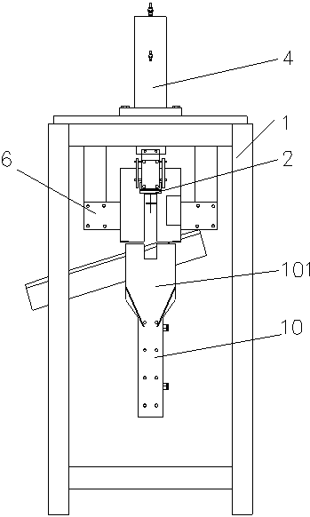
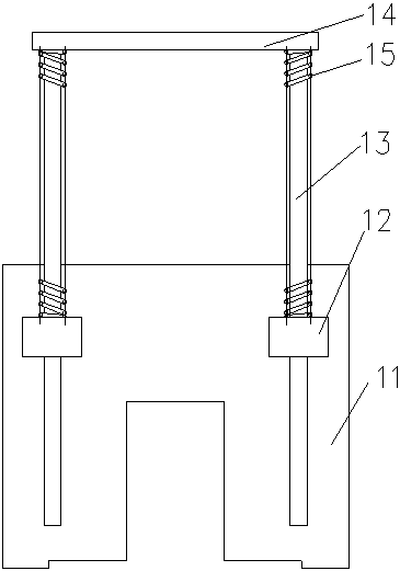
[0020] Such as Figure 1-2 As shown, the present invention comprises frame 1, feed guide rail 2, vibrator 3, oil cylinder 4, punching knife, mold 5, two clamping cylinders 6, finger cylinder 7, pulling material cylinder 8, drawing plate cylinder 10 and return material Cylinder 9. The described feeding guide rail 2, oil cylinder 4, mold 5, two clamping cylinders 6, material pulling cylinder 8 and material returning cylinder 9 are fixedly installed on the frame 1. The square section of the feed guide rail 2 is I-shaped, and the split ring is hung on the feed guide rail 2 . The discharge end of the feed guide rail 2 is slightly lower than the feed end, and a baffle 11 is provided at the discharge end. Such as Figure 3-4 As shown, the baffle plate 11 is provided with two sliding seats 12 (the number of sliding seats 12 can also be more than two), and the two sliding s...


PUM


Abstract

The invention discloses a full-automatic punching machine for ends of annular pipes. The full-automatic punching machine comprises a rack, a feeding guide rail, a vibrator, an oil cylinder, a punchingknife, a mold, two clamping air cylinders, a finger air cylinder, a pulling air cylinder, a pull plate air cylinder and a material return air cylinder. The feeding guide rail, the oil cylinder, the mold, the two clamping air cylinders, the pulling air cylinder and the material return air cylinder are fixedly mounted on the rack, a baffle is arranged at the discharging end of the feeding guide rail, and the vibrator is fixedly mounted on the feeding guide rail. The oil cylinder is fixed over the mold, the punching knife is arranged in a punching knife guide hole, and the upper end of the punching knife is connected with a piston rod of the oil cylinder. The two clamping air cylinders are located on the two sides of the mold, the pulling air cylinder and the material return air cylinder areparallel to a feeding trough on the mold, and the pull plate air cylinder is connected with a piston rod of the pulling air cylinder. The finger air cylinder is fixedly mounted at the end of a pistonrod of the material return air cylinder. The full-automatic punching machine is simple in structure and convenient to operate, mechanization and automation of punching of the ends of the annular pipes are achieved, the manual cost is reduced, and the product cost is reduced.

Description

technical field [0001] The invention belongs to the technical field of pipe punching equipment, and in particular relates to a fully automatic punching machine for the end of an annular pipe. Background technique [0002] The existing double-ring structure is often used for decoration in the existing protective windows and guardrails. The existing double-ring structure is divided into two types of welding structures. One is to weld an open ring into a whole ring first, and the other ring is divided into two arc-shaped parts. An arc portion less than 180° is welded inside the entire ring, and another arc portion greater than 180° is welded outside the entire ring. This kind of double-ring processing has complicated operation, low production efficiency and high cost, and has basically been eliminated. [0003] The other is two split rings, which are inserted into each other through their respective openings, and then welded into a double-ring structure. In the double ring pr...

Claims


Application Information

Patent Timeline
Patent Type & Authority Applications(China)
IPC IPC(8): B21D28/34B21D28/28B21D43/04B21D45/04
CPCB21D28/34B21D28/28B21D43/04B21D45/04
Inventor 汤文
Owner 汤文
Features
  • Generate Ideas
  • Intellectual Property
  • Life Sciences
  • Materials
  • Tech Scout
  • Unparalleled Data Quality
  • Higher Quality Content
  • 60% Fewer Hallucinations
Learn More