Self-heating assembly and bottle comprising self-heating assembly

A technology of self-heating and components, applied in food heating containers, packaging, packaged food, etc., can solve problems that are not conducive to mass production and environmental protection, self-heating devices cannot be recycled, and safety performance cannot be used. The heating operation is convenient, the processing cost is low, and the effect of energy loss is small

Pending Publication Date: 2020-06-05
INST OF MECHANICS - CHINESE ACAD OF SCI
View PDF3 Cites 0 Cited by
  • Summary
  • Abstract
  • Description
  • Claims
  • Application Information

AI Technical Summary

Problems solved by technology

The operation process of the beverage heating device is cumbersome, and there are many steps for the user to use, and a large amount of gas will be generated due to the reaction between the water bag and the heat-generating substance. These high-temperature gases are easy to explode in a closed space, causing harm to the drinker
Chinese patent 201610291663.2 discloses a two-piece can for self-cooling / self-heating. It is a piece-can structure, and the self-heating device installed in it can easily scratch the plastic film by mistake, and accidentally start the self-heating program
Chinese patent 201920374880.7 discloses a drinking bottle with a self-heating device, including a bottle with an upper body and a lower body and a self-heating device inside the bottle, but the self-heating device is integrated with the drinking bottle, After drinking the beverage bottle, the self-heating device cannot be recycled, which is not environmentally friendly
[0005] To sum up, the problems they have are that the self-heating device and the beverage bottle are integrated and cannot be disassembled separately, and the self-heating device cannot be recycled, which is not conducive to mass production and environmental protection; in addition, after the self-heating reaction substance generates heat, The heating parts are all at the bottom or outer circumference of the bottle, which easily brings the risk of scalding to the drinker, and the most basic safety performance cannot meet the requirements of use

Method used


Image

  • Self-heating assembly and bottle comprising self-heating assembly
  • Self-heating assembly and bottle comprising self-heating assembly
  • Self-heating assembly and bottle comprising self-heating assembly

Examples


Embodiment Construction

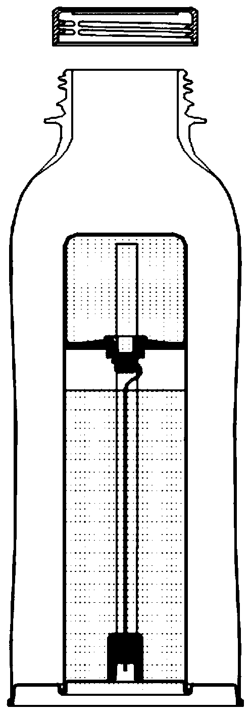
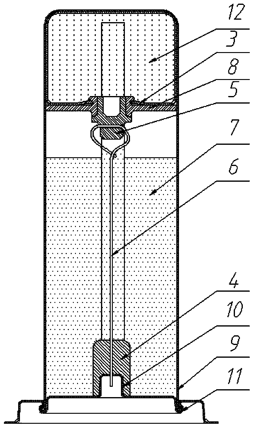
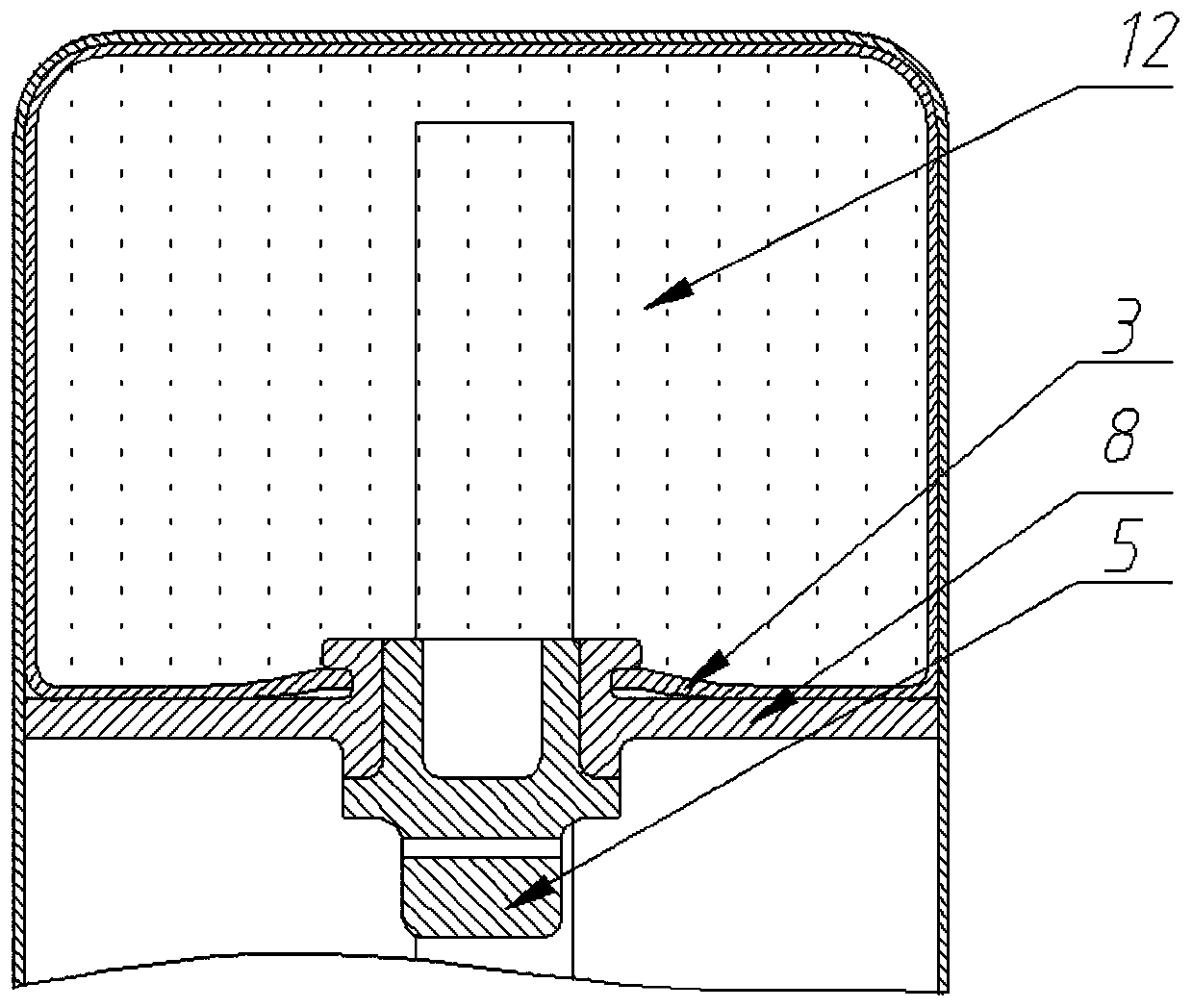
[0038] In order to make the purpose, technical solutions and advantages of the present invention clearer, the present invention will be further described in detail below in conjunction with the examples and accompanying drawings. As a limitation of the present invention.

[0039] It should be noted that, in the description of the present invention, the terms "horizontal", "vertical", "upper", "lower", "front", "rear", "left", "right", "vertical", The orientation or positional relationship indicated by "horizontal", "top", "bottom", "inner", "outer", etc. is based on the orientation or positional relationship shown in the drawings, and is only for the convenience of describing the present invention and simplifying the description, and It is not to indicate or imply that the device or element referred to must have a particular orientation, be constructed in a particular orientation, or operate in a particular orientation, and thus should not be construed as limiting the inventio...


PUM


Abstract

The invention discloses a self-heating assembly and a bottle comprising the self-heating assembly. The self-heating assembly comprises a closed shell, a supporting device, a reactant group, a tractiondevice, an elastic material and the like, wherein at least two separately arranged reactants in the shell can be contacted to generate heat. The self-heating assembly is independently manufactured and can be arranged in inner cavities of various bottle bodies, the contact area between reaction substances and heated beverages or water in the bottle bodies is increased, the external temperature ofthe bottle bodies is reduced, the danger of scalding can be greatly avoided, the advantage of small energy loss is achieved, and the defects that an existing self-heating beverage bottle is high in production cost, insufficient in safety performance, not suitable for mass production and the like are effectively overcome.

Description

technical field [0001] The invention relates to the technical field of self-heating, in particular to a self-heating component and a bottle including the self-heating component. Background technique [0002] Bottled drinks are not only convenient to drink but also easy to carry. They are the first choice for everyone to go out. However, the temperature of this type of drink is generally close to the ambient temperature. In cold winter or when you are usually unwell, drinking a drink with a low temperature will aggravate people's cold feeling and even cause gastrointestinal discomfort. Especially in the cold environment, when people drink beverages, they all hope to drink hot beverages or water, and need to carry extra heating equipment, which is very inconvenient. [0003] At present, there are also some patented technologies for heating beverage bottles or self-heating beverage bottles on the market, but after careful investigation, it is found that they all have correspon...

Claims


Application Information

Patent Timeline
Patent Type & Authority Applications(China)
IPC IPC(8): B65D81/34
CPCB65D81/3453
Inventor 苏业旺马远良
Owner INST OF MECHANICS - CHINESE ACAD OF SCI
Why Eureka
Try Eureka