Fixed aviation kerosene gas recovery system

A recovery system, coal oil and gas technology, applied in liquid hydrocarbon mixture recovery, petroleum industry, etc., can solve problems such as difficulty in exerting optimal performance, low life of activated carbon, high power consumption cost, etc., to prevent clogging, reduce floor space, The effect of improving cooling performance

Pending Publication Date: 2020-06-05
中国人民解放军军事科学院国防工程研究院工程防护研究所
View PDF0 Cites 1 Cited by
  • Summary
  • Abstract
  • Description
  • Claims
  • Application Information

AI Technical Summary

Problems solved by technology

Currently available oil and gas recovery processes include condensation method, adsorption method, absorption method, and membrane separation method, but using one of them alone for oil and gas recovery often has problems such as high cost and low efficiency
[0003] In the existing condensation method, in order to meet the increasingly stringent international and local emission standards, high-level cryogenics are required. A three-stage refrigeration system is used to gradually cool down the oil and gas, and most of the light hydrocarbon components are liquefied for recovery. However, this method requires Pay a higher price for power consumption
[0004] The existing activated carbon adsorption methods mainly include pressure swing adsorption and temperature swing adsorption. Both methods have advantages and disadvantages. The influence of temperature is large, and it is difficult to achieve the best performance in practical applications; temperature swing adsorption completes desorption through high temperature, and the desorption is relatively clean, but the life of activated carbon is short and the operating cost is high

Method used


Image

  • Fixed aviation kerosene gas recovery system
  • Fixed aviation kerosene gas recovery system
  • Fixed aviation kerosene gas recovery system

Examples


Embodiment Construction

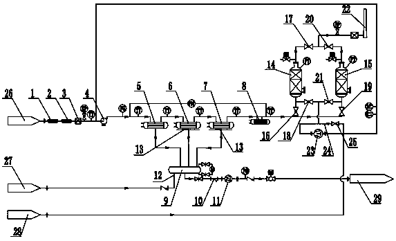
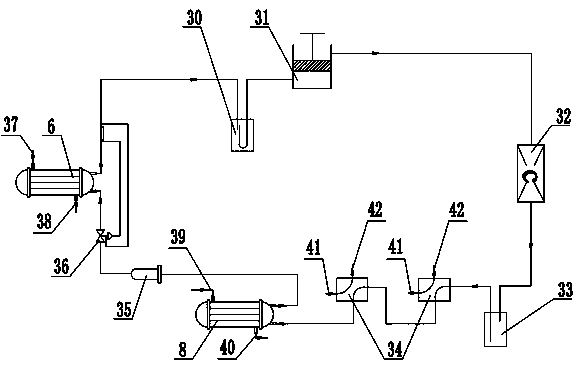
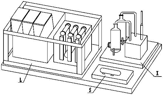
[0032] The specific implementation manners of the present invention will be further described in detail below in conjunction with the accompanying drawings.

[0033] Such as figure 1 , figure 2 , image 3 As shown, a fixed aviation fuel oil and gas recovery system includes three modules: a conveying system S, a condensation system L, and an adsorption system X. The conveying system S includes an oil and gas collection system 1, a gas-liquid separation system 2, and a conveying power system; the condensation system L includes a three-stage independent refrigeration system composed of the first-stage refrigeration system, the second-stage refrigeration system and the third-stage refrigeration system, an oil storage tank 9 and an oil discharge system; the adsorption system X includes adsorption tank A14, adsorption tank B15, and vacuum pump 23 , chimney 22, adsorption electric valve, desorption electric valve I;

[0034] In the delivery system S, the inlet of the oil and gas ...


PUM


Abstract

The invention discloses a fixed aviation kerosene gas recovery systemwhich comprises a conveying system, a condensation system and an adsorption system three modules;the conveying system comprises anoil-gas collection system, a gas-liquid separation system and a conveying power system, and the condensation system comprises a three-stage independent refrigeration systemcomposed of a first-stage refrigeration system, a second-stage refrigeration system and a third-stage refrigeration system, an oil storage tank and an oil discharge system; the adsorption system comprisesadsorption tanks, a vacuum pump, an adsorption electric valve and a desorption electric valve. A condensation method and an adsorption method are combined, all modules of the oil gas recovery system are integrated on an integral base through a skid-mounted structure, the condensation system adopts thethree-stage independent refrigeration system to conduct graded cooling condensation on oil gas, and condensed oil is collected in the same oil storage tank through three different pipelines; and meanwhile, the adsorption system continuously adsorbs the oil gas by adopting a mode that the two adsorption tanks are alternately operated, so that the efficiency of the oil gas recovery system is improved, and the oil gas recovery cost is reduced.

Description

technical field [0001] The invention belongs to the technical field of oil and gas recovery, and in particular relates to a fixed aviation fuel oil and gas recovery system. Background technique [0002] When the aircraft refueling truck is loading fuel in the oil depot, a large amount of oil and gas will be volatilized. In order to prevent such oil and gas from being directly discharged into the atmosphere to cause environmental pollution, an oil and gas recovery system is needed to collect the volatilized oil and gas. Currently available oil and gas recovery processes include condensation, adsorption, absorption, and membrane separation methods, but using one of these methods alone for oil and gas recovery often has problems such as high cost and low efficiency. [0003] In the existing condensation method, in order to meet the increasingly stringent international and local emission standards, high-level cryogenics are required. A three-stage refrigeration system is used t...

Claims


Application Information

Patent Timeline
Patent Type & Authority Applications(China)
IPC IPC(8): C10G5/06C10G5/02
CPCC10G5/02C10G5/06
Inventor 陈叶青汪剑辉赵强陈经郭利平邱鸿
Owner 中国人民解放军军事科学院国防工程研究院工程防护研究所
Why Eureka
Try Eureka