A textile yarn dyeing processing system

A processing system and textile yarn technology, applied in the field of yarn textile production, can solve problems such as yarn not waiting for drying in time, yarn contact parts fusing or scorching, and yarn color difference, etc., to achieve improved The degree of drying uniformity, avoiding fusing or scorching marks, and avoiding the effect of uneven dyeing liquor

Active Publication Date: 2021-06-11
浙江志达服装有限公司
View PDF0 Cites 0 Cited by
  • Summary
  • Abstract
  • Description
  • Claims
  • Application Information

AI Technical Summary

Problems solved by technology

[0003] 1. When immersing bundled and other overall forms of yarn in the dyeing solution in a static state for dyeing treatment, the dyeing solution that has been standing for a long time is prone to delamination, resulting in uneven color and mottled yarns. The phenomenon, and the degree of dyeing inside and outside the yarn bundle is different, which will easily lead to a low degree of uniform dyeing of the overall yarn. At the same time, the dyeing and drying process of the yarn is not continuous, so that the yarn cannot be dried in time, and the yarn Lines are prone to dark and light color separation areas;
[0004] 2. When monofilaments are dyed side by side, dried, and rolled into shape, the initial winding section of the yarn is not dyed, and this colorless section forms a mixed winding state with the subsequent dyed yarn, thereby reducing the dyed yarn formed. At the same time, during the yarn drying process, the yarn tends to be in a loose state, which causes the yarn to contact the drying structure, and then fuses or scorch marks appear on the contact part of the yarn, and the wrinkles on the loose yarn are easy to make the yarn The drying degree of the yarn is different, and the yarn is prone to have different shades in the end

Method used


Image

  • A textile yarn dyeing processing system
  • A textile yarn dyeing processing system
  • A textile yarn dyeing processing system

Examples


Embodiment Construction

[0034] The embodiments of the present invention will be described in detail below in conjunction with the accompanying drawings, but the present invention can be implemented in many different ways that are predetermined and covered by the claims.

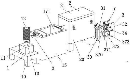
[0035] Such as Figure 1 to Figure 10 As shown, a textile yarn dyeing treatment system includes a dyeing mechanism 1, a drying mechanism 2 and a retracting mechanism 3. A drying mechanism 2 is arranged on the right side of the dyeing mechanism 1, and the front side of the drying mechanism 2 is The right side is provided with a retracting mechanism 3, and the lower end of the dyeing mechanism 1, the lower end of the drying mechanism 2 and the lower end of the retracting mechanism 3 are all installed on the existing working ground.

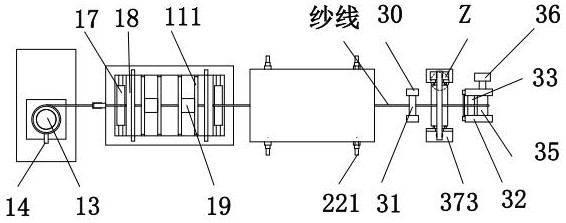
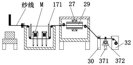
[0036] The dyeing mechanism 1 includes a base 10, a No. 1 motor 11, a fixed shaft 12, an original thread barrel 13, a bayonet pin 14, a dyeing pool 15, a shaft 16, a No. 1 rotating shaft 17, a No. 2 rotat...


PUM


Abstract

The invention relates to a textile yarn dyeing treatment system, comprising a dyeing mechanism, a drying mechanism and a winding mechanism, a drying mechanism is arranged on the right side of the dyeing mechanism, and a winding mechanism is arranged on the right side of the drying mechanism. Mechanism, the lower end of the dyeing mechanism, the lower end of the drying mechanism and the lower end of the winding mechanism are all installed on the existing working ground. The present invention adopts the design concept of dyeing-drying-winding integrated structure to carry out the yarn dyeing process, wherein Both the dyeing mechanism and the drying mechanism are equipped with a rotatable structure to improve the uniformity of dyeing and drying of the dyed yarn. At the same time, the dyed yarn and the initial colorless yarn can be wound separately, so that Improved build quality of dyed yarn bobbins.

Description

technical field [0001] The invention relates to the technical field of yarn textile production, in particular to a textile yarn dyeing treatment system. Background technique [0002] Yarn is a kind of textile, which is processed into products of a certain fineness with various textile fibers. It is used for weaving, rope making, thread making, knitting and embroidery, etc. It is divided into staple fiber yarn, continuous filament, etc. There are many varieties and different properties. It can be pure spinning made of natural fibers or various chemical short fibers, or a blended yarn made of several fibers, or it can be directly sprayed from chemical fibers. The processed filament yarn can usually be classified according to the raw materials used in the yarn, the thickness of the yarn, the spinning method, the spinning system, the structure of the yarn and the use of the yarn, etc. The yarn can be divided according to the process, which is divided into Pure spinning, blended...

Claims


Application Information

Patent Timeline
Patent Type & Authority Patents(China)
IPC IPC(8): D06B3/04D06B15/00D06B23/00D06B23/04D06B23/20D06H7/00D02J7/00
CPCD02J7/00D06B3/04D06B15/00D06B23/00D06B23/04D06B23/20D06H7/00
Inventor 陈蓓蓓谷珍妮
Owner 浙江志达服装有限公司
Why Eureka
Try Eureka