Wellhead return system and method for water injection well in oil field

A technology of water injection and water reinjection in oilfields, which is applied in the direction of wellbore/well components, production fluid, earthwork drilling and production, etc. It can solve the problems of insufficient reinjection water, achieve the solution of substandard water quality, simple process flow, and flexible working condition adjustment Effect

Active Publication Date: 2021-11-05
SOUTHWEST PETROLEUM UNIV
View PDF16 Cites 0 Cited by
  • Summary
  • Abstract
  • Description
  • Claims
  • Application Information

AI Technical Summary

Problems solved by technology

[0006] The invention provides a wellhead return system and method for water injection wells in oil fields, which solves the problem of insufficient daily reinjection water required by the combined station after the reinjection water flow rate

Method used


Image

  • Wellhead return system and method for water injection well in oil field
  • Wellhead return system and method for water injection well in oil field
  • Wellhead return system and method for water injection well in oil field

Examples


Embodiment Construction

[0044] The present invention will be further described below in conjunction with the accompanying drawings and embodiments.

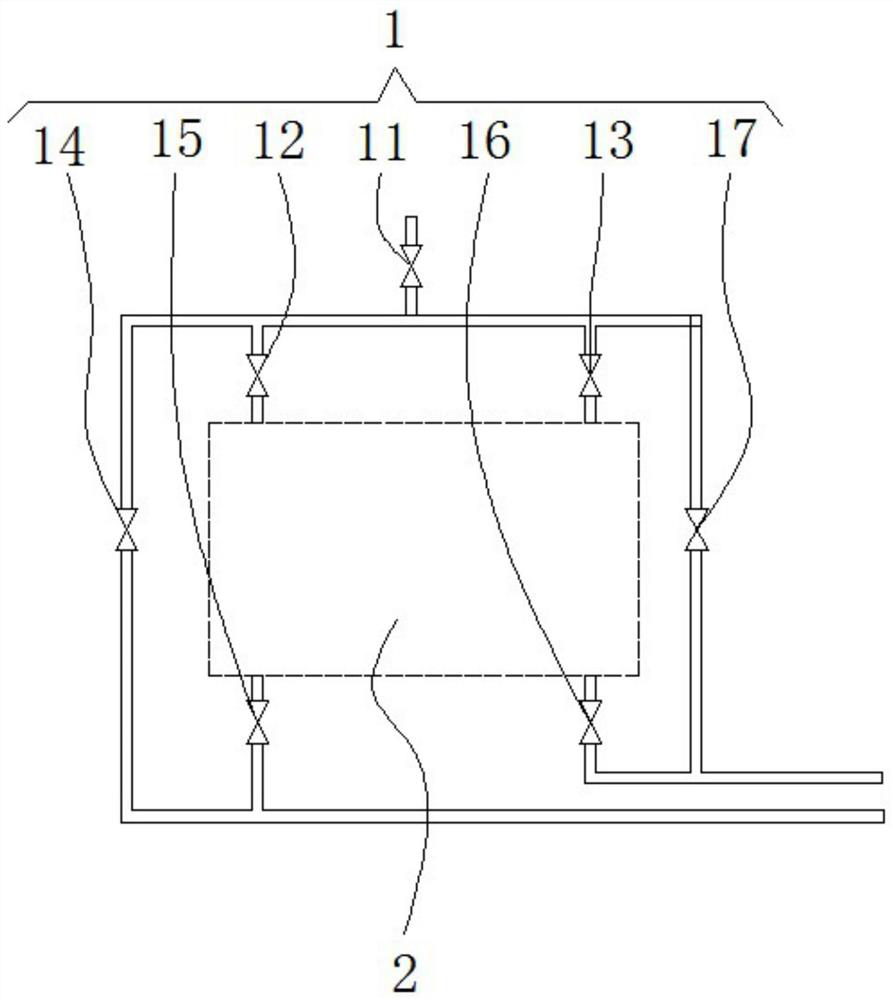
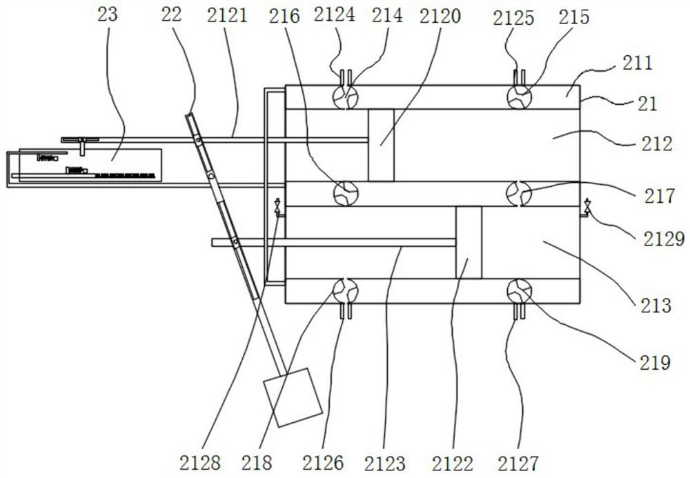
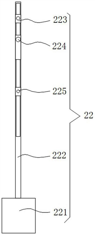
[0045] Please refer to figure 1 , figure 2 , image 3 , Figure 4 , Figure 5 and Figure 6 ,in, figure 1 A structural schematic diagram of a preferred embodiment of the oil field water injection well wellhead return system and method provided by the present invention; figure 2 It is a schematic cross-sectional view of the wellhead backflow device; image 3 It is a schematic cross-sectional view of the pendulum mechanism of the wellhead reflux device; Figure 4 It is a schematic cross-sectional view of the movement transformation mechanism of the wellhead reflux device; Figure 5 It is a schematic cross-sectional diagram of the timing mechanism of the wellhead backflow device; Figure 6 It is a schematic diagram of the timing ratchet of the timing mechanism. The wellhead return system and method of oilfield water injection well include:

[...


PUM


Abstract

The invention provides a wellhead return flow system and method of a water injection well in an oil field. The oilfield water injection well wellhead return system and method include: a wellhead flow regulating device and a wellhead return device; the wellhead flow regulating device includes a first gate valve, a second gate valve, a third gate valve, a fourth gate valve, a fifth gate valve, a sixth The gate valve and the seventh gate valve, the first gate valve is connected to the reinjection water incoming water pipeline, and the first gate valve is respectively connected in series with the fourth gate valve and the seventh gate valve through the pipeline. The wellhead return system and method of oilfield water injection wells provided by the present invention can realize the return flow of reinjection water from the water injection well to the combined station, facilitate the rapid transportation of the reinjected water from the combined station to the water injection well, improve the water quality of the reinjected water, and effectively solve the problem of It solves the problem that the content of suspended solids at the wellhead of the water injection well and the median particle size are not up to the standard, and has the advantages of simple structure, convenient operation, and easy maintenance.

Description

technical field [0001] The invention relates to the field of oilfield reflux, in particular to an oilfield water injection well wellhead reflux system and method. Background technique [0002] According to the statistical analysis of OPEC, the global daily oil consumption in 2015 was 86.5×10⁶ barrels / day, and by 2040, the global daily oil consumption will reach 100.7×10⁶ barrels / day, and the water content of current oil fields generally exceeds 75%. The oil field is even more than 95%. Domestically, according to the analysis of Academician Han Dakuang and Academician Li Yang, the reserves and output of my country's water injection oilfields account for more than 80% of the total, and the average water content of oilfields exceeds 86.0%. Therefore, a large amount of by-product—produced water—is produced in the process of oilfield exploitation. [0003] In order to avoid the impact of produced water on the environment and maintain the pressure balance of the reservoir, accor...

Claims


Application Information

Patent Timeline
Patent Type & Authority Patents(China)
IPC IPC(8): E21B43/20
CPCE21B43/20
Inventor 李桂亮李长俊曹斌谢含宇何杰
Owner SOUTHWEST PETROLEUM UNIV
Why Eureka
Try Eureka