Method for accurately controlling and repairing cutting length in optical fiber welding process

A technology of cutting length and precise control, applied in the coupling of optical waveguides, optics, light guides, etc., can solve the problems of scrapped optical fibers, the blade of the optical fiber cleaver is not adjusted properly, and the optical fibers cannot meet the requirements, and achieves safe and convenient use. Avoid equipment scrap, good effect

Active Publication Date: 2020-06-05
青岛自贸激光科技有限公司
View PDF6 Cites 4 Cited by
  • Summary
  • Abstract
  • Description
  • Claims
  • Application Information

AI Technical Summary

Problems solved by technology

[0002] In the process of optical fiber fusion, it is necessary to peel off the coating layer of the optical fiber and clean the residue of the coating layer. After the surface treatment of the optical fiber is completed, the end face of the optical fiber needs to be cut. Generally, a fiber cleaver is used. The working principle of the fiber cleaver is mainly stress For cutting and ultrasonic cutting, both ends of the optical fiber must be fixed during cutting. Each cutting has a minimum fiber cutting length for fixing the fiber. Generally, household optical fibers do not have high requirements for fiber cutting length, but in some fields that need to control the length of the fiber , especially the fusion splicing that needs to precisely control the length of the fiber, such as the optical path fusion splicing in the fiber laser resonator, the optical path fusion splicing of the time division multiplexing module, etc. Some problems often occur in the fusion splicing process that requires precise control of the fiber length. Although the cutting knife There is a ruler, which can control the length of the optical fiber, but when the measurement is fixed and the cutting is performed, errors will occur, or the blade of the optical fiber cleaver is not adjusted properly, resulting in the cut optical fiber failing to meet the requirements, such as the length after cutting is less than the design required length , or the length after cutting is greater than the design requirement, the length of the fiber will meet, but the end face of the fiber is not flat. Disposal of connected devices

Method used


Image

  • Method for accurately controlling and repairing cutting length in optical fiber welding process
  • Method for accurately controlling and repairing cutting length in optical fiber welding process
  • Method for accurately controlling and repairing cutting length in optical fiber welding process

Examples


Embodiment 1

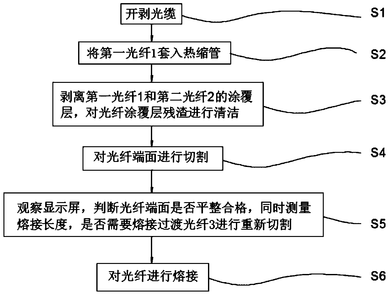
[0035] Embodiment 1: as figure 1 , a method for precisely controlling and repairing the cutting length in the process of optical fiber fusion, the method includes the following steps:

[0036] S1, stripping the optical cable;

[0037] S2. Insert the first optical fiber 1 into the heat shrinkable tube;

[0038] S3, peeling off the coating layer of the first optical fiber 1 and the second optical fiber 2, and cleaning the residue of the optical fiber coating layer;

[0039] S4, cutting the end face of the optical fiber;

[0040] S5. Observe the display screen to determine whether the end face of the optical fiber is flat and qualified, and measure the length of the fusion splicing at the same time, whether it is necessary to re-cut the fusion splicing transition optical fiber 3;

[0041] S6. Splicing the optical fibers.

[0042] In step S1, after the optical cable is stripped, the optical cable needs to be fixed in the splice box, and inserted into the splice box, and the fi...

Embodiment 2

[0055] Embodiment 2: as figure 1 , a method for precisely controlling and repairing the cutting length in the process of optical fiber fusion, the method includes the following steps:

[0056] S1, stripping the optical cable;

[0057] S2. Insert the first optical fiber 1 into the heat shrinkable tube;

[0058] S3, peeling off the coating layer of the first optical fiber 1 and the second optical fiber 2, and cleaning the residue of the optical fiber coating layer;

[0059] S4, cutting the end face of the optical fiber;

[0060] S5. Observe the display screen to determine whether the end face of the optical fiber is flat and qualified, and measure the length of the fusion splicing at the same time, whether it is necessary to re-cut the fusion splicing transition optical fiber 3;

[0061] S6. Splicing the optical fibers.

[0062] In step S1, after the optical cable is stripped, the optical cable needs to be fixed in the splice box, and inserted into the splice box, and the fi...

Embodiment 3

[0075] Embodiment 3: as figure 1 , a method for precisely controlling and repairing the cutting length in the process of optical fiber fusion, the method includes the following steps:

[0076] S1, stripping the optical cable;

[0077] S2. Insert the first optical fiber 1 into the heat shrinkable tube;

[0078] S3, peeling off the coating layer of the first optical fiber 1 and the second optical fiber 2, and cleaning the residue of the optical fiber coating layer;

[0079] S4, cutting the end face of the optical fiber;

[0080] S5. Observe the display screen to determine whether the end face of the optical fiber is flat and qualified, and measure the length of the fusion splicing at the same time, whether it is necessary to re-cut the fusion splicing transition optical fiber 3;

[0081] S6. Splicing the optical fibers.

[0082] In step S1, after the optical cable is stripped, the optical cable needs to be fixed in the splice box, and inserted into the splice box, and the fi...


PUM


Abstract

The invention particularly discloses a method for accurately controlling and repairing a cutting length in an optical fiber welding process. The invention belongs to the technical field of optical fiber cutting and welding. The method is scientific and reasonable, safe and convenient use. for the problems that after the optical fiber is cut by using an optical fiber cutting machine, the length ofan optical fiber is larger than a designed length and smaller than the designed length, the cutting surface of the optical is not even and the welding requirements are not met, a section of transitionoptical fiber is welded on the optical fiber, then cutting is performed, and the original optical fiber is welded, so that the scrapping condition of the original optical fiber and the original optical fiber connecting device is avoided, when the optical fiber cutting knife is used for cutting the optical fiber, the cutting length of the optical fiber is accurately measured, the optical fiber isfixed through an optical fiber guide groove, a small pressing plate and a pressing rod on the optical fiber cutting knife and carefully operated, the error phenomenon generated when the optical fibercutting knife cuts the optical fiber is avoided, equipment scrapping caused by misoperation in the actual operation process is avoided, losses are reduced, and the effect is good.

Description

technical field [0001] The invention relates to the technical field of optical fiber cutting and welding, in particular to a method for precisely controlling and repairing the cutting length during the optical fiber welding process. Background technique [0002] In the process of optical fiber fusion, it is necessary to peel off the coating layer of the optical fiber and clean the residue of the coating layer. After the surface treatment of the optical fiber is completed, the end face of the optical fiber needs to be cut. Generally, a fiber cleaver is used. The working principle of the fiber cleaver is mainly stress For cutting and ultrasonic cutting, both ends of the optical fiber must be fixed during cutting. Each cutting has a minimum fiber cutting length for fixing the fiber. Generally, household optical fibers do not have high requirements for fiber cutting length, but in some fields that need to control the length of the fiber , especially the fusion splicing that need...

Claims


Application Information

Patent Timeline
Patent Type & Authority Applications(China)
IPC IPC(8): G02B6/255G02B6/25
CPCG02B6/2551G02B6/25Y02P40/57
Inventor 罗文清汪家乐尚俊杰
Owner 青岛自贸激光科技有限公司
Why Eureka
Try Eureka