
Pulse electrospray ion source, pulse sample injection method and mass spectrum detection system

A pulsed electricity and ion source technology, applied in the field of analytical instruments, can solve the problem of low sample utilization rate, and achieve the effects of short response time, improved utilization rate, and small sample consumption

Inactive Publication Date: 2020-06-05
SHENZHEN GRADUATE SCHOOL TSINGHUA UNIV
View PDF9 Cites 4 Cited by
  • Summary
  • Abstract
  • Description
  • Claims
  • Application Information

AI Technical Summary

Problems solved by technology

In the specific operation, it is necessary to use auxiliary devices such as pipette guns and syringe pumps to inject samples, and then power up in pulses for ionization, that is, sample injection and ionization are asynchronous processes, and the sample utilization rate is not high.

Method used


Image

  • Pulse electrospray ion source, pulse sample injection method and mass spectrum detection system
  • Pulse electrospray ion source, pulse sample injection method and mass spectrum detection system

Examples


Embodiment 1

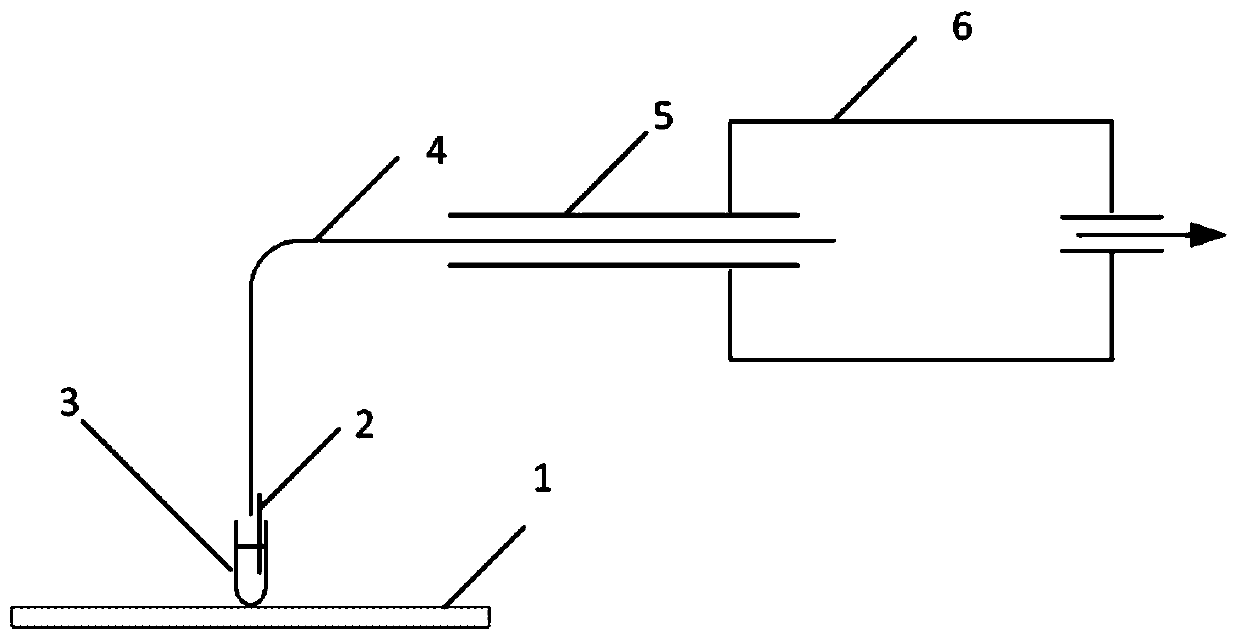
[0043] Such as figure 1 Shown is a schematic structural view of the pulsed electrospray ion source in this specific embodiment. It includes a sampling capillary 4, a carrier gas channel 5, an elevating platform 1, an electrode 2, a centrifuge tube 3, and a low-pressure chamber 6.

[0044] One end of the sampling capillary 4 is used as the sampling end, and the other end is placed in the low-pressure cavity 6; the sampling capillary 4 passes through the carrier gas passage 5; the electrode 2 is inserted into the solution in the centrifuge tube 3; the The electrode 2 and the centrifuge tube 3 are placed together on the lifting platform 1; the lifting platform 1 can move up and down or three-dimensionally; the other end of the low-pressure cavity 6 is connected to the sample inlet of the mass spectrometer. The capillary 4 is in pulsed contact with the sample to be measured, and self-priming sample injection can generate pulsed electrospray in the low-pressure chamber 6, so that ...

Embodiment 2

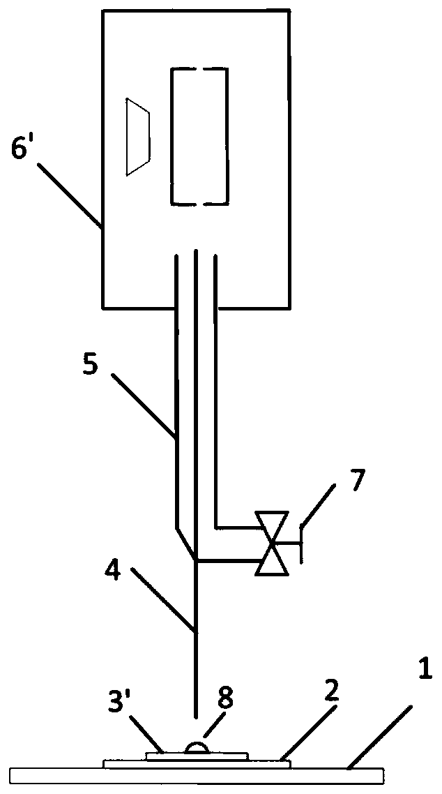
[0046] Such as figure 2 As shown, it includes a sample injection capillary 4, a carrier gas channel 5, a gas path valve 7, a lifting platform 1, an electrode 2, a sample plate 3', and a mass spectrometer cavity 6'.

[0047] One end of the sampling capillary 4 is used as the sampling end, the other end is placed in the cavity 6' of the mass spectrometer, the sampling capillary 4 passes through the carrier gas passage 5; the electrode 2 is placed under the sample plate 3, The droplet 8 to be tested is placed on the sample plate 3'; the electrode 2 and the sample plate 3' are placed together on the lift table 1; the lift table 1 can move up and down or three-dimensionally; the gas circuit valve 7 intermittently The capillary 4 is pulsed to contact the sample to be tested. When the droplet to be tested is transported to the end of the capillary 4, the gas valve 7 is opened instantaneously to promote the desolvation process of the electrospray, and finally the sample is detected b...


PUM


Abstract

The invention discloses a pulse electrospray ion source, a pulse sample injection method and a mass spectrum detection system. The ion source comprises a sample supply appliance, a sample injection capillary tube and an electrode, and a sample solution provided by the sample supply appliance enters from the sample injection end of the sample injection capillary tube and is output from the output end of the sample injection capillary; the electrode electrifies the sample solution so as to provide voltage required for forming electrospray; the ion source also comprises a moving device coupled tothe sample supply appliance or the sample introduction capillary, during sample injection, the sample supply device and the sample injection capillary tube intermittently move relative to each otheraccording to a set pulse time sequence, so that a sample in the sample supply device is intermittently contacted with the sample injection end of the sample injection capillary tube, and pulse type electrospray sample injection is realized. According to the invention, pulse sample injection and ionization are synchronously carried out, and the sample utilization rate is improved.

Description

technical field [0001] The invention relates to the field of analytical instruments, in particular to a pulsed electrospray ion source and a pulsed sampling method. Background technique [0002] Mass spectrometer has a history of more than 100 years since its invention, and has been widely used because of its high sensitivity, high accuracy, fast analysis speed and strong qualitative ability. The ion source is one of the core components of the mass spectrometer, which determines the detection range and sensitivity of the instrument. Among them, the electrospray ion source is the most widely used ion source, and its technology has won the Nobel Prize. [0003] The working process of electrospray can be simply described as: the sample solution passes through the capillary at a low flow rate. A high voltage is connected to the capillary, and the positive or negative of the voltage depends on the nature of the analyte. The voltage provides the electric field gradient required...

Claims


Application Information

Patent Timeline
Patent Type & Authority Applications(China)
IPC IPC(8): H01J49/16H01J49/26
CPCH01J49/167H01J49/26
Inventor 余泉张乾王晓浩
Owner SHENZHEN GRADUATE SCHOOL TSINGHUA UNIV
Learn More