
Well lid type ground antenna device

A ground antenna and manhole cover technology, applied in the field of communication, can solve the problems of aging, accelerated antenna, blind area and weak area, etc., and achieve the effect of light weight, good concealment, and convenient mass production

Inactive Publication Date: 2020-06-05
安徽泊仙科技有限公司
View PDF0 Cites 2 Cited by
  • Summary
  • Abstract
  • Description
  • Claims
  • Application Information

AI Technical Summary

Problems solved by technology

[0002] With the promotion of 5G signals and people's higher and higher requirements for instant messaging, there are more and more communication base station construction sites. However, for places with high population density and other places where it is not convenient to build medium and large base stations, it is necessary to adopt multi-point scattered layout. For the solution of small antennas, for high-rise buildings, roof antennas can be arranged to solve signal blind spots, but for conventional low-rise or square areas, residents also have a strong resistance to electromagnetic wave radiation, resulting in a large number of conflicts and conflicts, resulting in many base stations being blocked. Forced to dismantle it, unable to build a station and forming a blind area and weak area of ​​network coverage, resulting in a large number of complaints, and finally causing a dilemma for operators. Secondly, the antenna will be exposed for a long time to accelerate the aging of the antenna. How to arrange the antenna to enhance the signal and at the same time not It will cause owners and other residents to resist the base station, which is an issue that should be paid attention to at the moment

Method used


Image

  • Well lid type ground antenna device
  • Well lid type ground antenna device
  • Well lid type ground antenna device

Examples


Embodiment Construction

[0023] The following will clearly and completely describe the technical solutions in the embodiments of the present invention with reference to the accompanying drawings in the embodiments of the present invention. Obviously, the described embodiments are only some, not all, embodiments of the present invention.

[0024] Examples of the described embodiments are shown in the drawings, wherein like or similar reference numerals designate like or similar elements or elements having the same or similar functions throughout. The embodiments described below by referring to the figures are exemplary and are intended to explain the present invention and should not be construed as limiting the present invention.

[0025] In describing the present invention, it should be understood that the terms "center", "longitudinal", "transverse", "length", "width", "thickness", "upper", "lower", "front", " Back", "Left", "Right", "Vertical", "Horizontal", "Top", "Bottom", "Inner", "Outer", "Clock...


PUM


Abstract

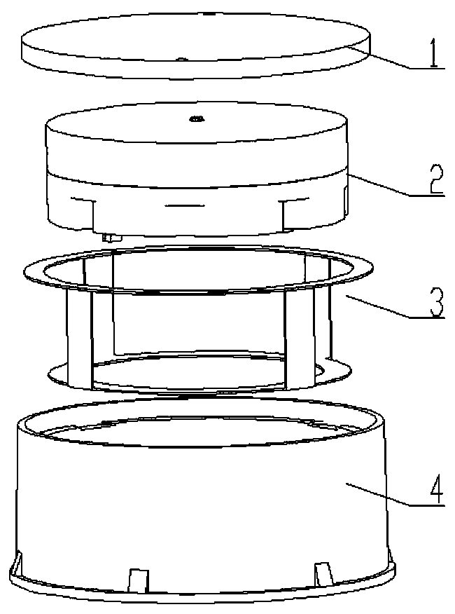
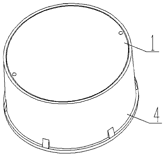
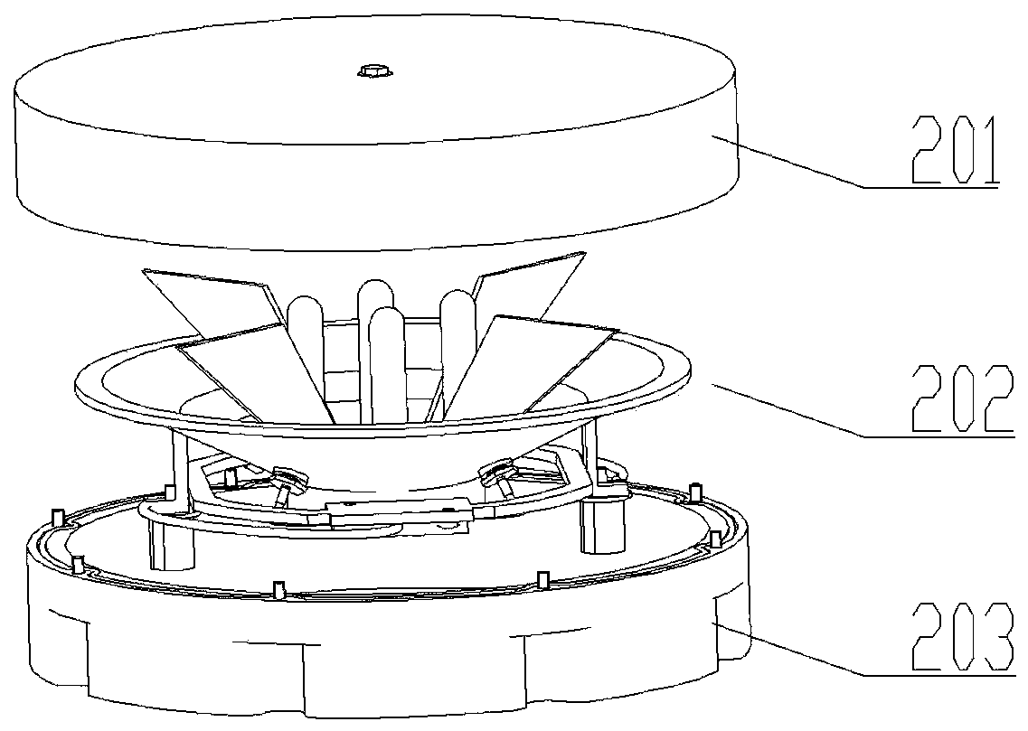
The invention discloses a well lid type ground antenna device. The well lid type ground antenna device comprises a cover plate, an antenna body, a supporting frame and a base, an upper mounting cavityis formed in the base, the supporting frame is arranged in the mounting cavity, the antenna body is mounted in the mounting cavity through the supporting frame, and the cover plate is mounted at theupper end in the base. According to the invention, the antenna bodies are integrally integrated and separated from the fixing device; the well lid type ground antenna device has the advantages of simple structure, small size and light weight, and workers can conveniently machine and fix step by step; and mass production is convenient, and meanwhile, the interchangeability of the antenna device isgood, wherein the antenna body is the core part of the whole device, only two cables are connected with the outside, if the antenna body needs to be replaced, only the antenna body needs to be replaced, installation is convenient, the upper antenna cover, the lower antenna cover and the connector of the antenna body are each of a waterproof structure, the cover plate is covered with the antenna body, only the cover plate is exposed out of the whole antenna device, the cover plate is in the well lid shape and style, and good concealment is achieved.

Description

technical field [0001] The invention relates to the technical field of communication, in particular to a manhole cover type ground antenna device. Background technique [0002] With the promotion of 5G signals and people's higher and higher requirements for instant messaging, there are more and more communication base station construction sites. However, for places with high population density and other places where it is not convenient to build medium and large base stations, it is necessary to adopt multi-point scattered layout. For the solution of small antennas, for high-rise buildings, roof antennas can be arranged to solve signal blind spots, but for conventional low-rise or square areas, residents also have a strong resistance to electromagnetic wave radiation, resulting in a large number of conflicts and conflicts, resulting in many base stations being blocked. Forced to dismantle it, unable to build a station and forming a blind area and weak area of ​​network cover...

Claims


Application Information

Patent Timeline
Patent Type & Authority Applications(China)
IPC IPC(8): H01Q1/22H01Q1/42H01Q1/50
CPCH01Q1/22H01Q1/42H01Q1/50
Inventor 尹丽娟
Owner 安徽泊仙科技有限公司
Learn More