Bridgeless PFC switching power supply circuit
A technology of switching power supply circuit and switching tube, applied in the field of power electronics, can solve the problems of difficulty in current sampling of bridgeless PFC circuit, cannot be directly applied to PFC controller, etc., and achieves simple current sampling signal processing, simple structure, and sampling current signal processing. simple effect
- Summary
- Abstract
- Description
- Claims
- Application Information
AI Technical Summary
Problems solved by technology
Method used
Image

Examples
no. 1 example
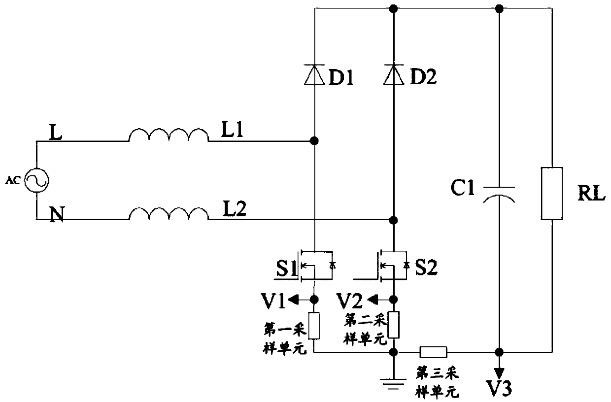
[0048] The circuit principle diagram of the bridgeless PFC switching power supply circuit of the first embodiment of the present invention is as follows Image 6 As shown, it is a bridgeless PFC switching power supply circuit and control method based on the current blocking of the switching tube, including: an AC input source AC, a first inductance L1 and a second inductance L2, and the first end of the first inductance L1 is connected to The first end of the AC input source AC, the first end of the second inductor L2 is connected to the second end of the AC input source AC;
[0049] Including: a first diode D1 and a second diode D2, a first switching tube Q1 and a second switching tube Q2, the second end of the first inductor L1 is connected to the anode of the first diode D1 and the first switching tube The drain of Q1, the second end of the second inductor L2 is connected to the anode of the second diode D2 and the drain of the second switching transistor Q2;
[0050] It i...
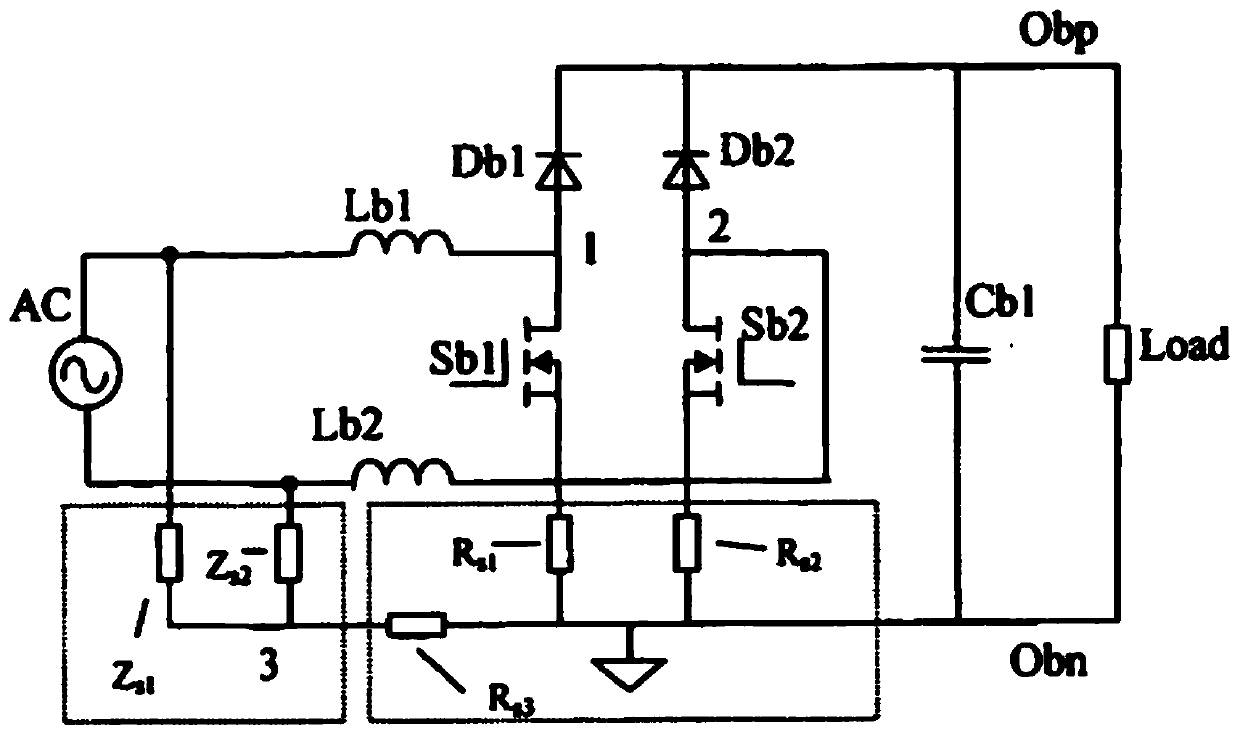
no. 2 example
[0069] In the above-mentioned first embodiment of the present invention, the bridgeless PFC switching power supply circuit uses the switching tube as the current blocking device. The second embodiment of the present invention is such as Figure 15 As shown, the difference from the first embodiment is that a diode is used as the current blocker.
[0070] A bridgeless PFC switching power supply circuit, comprising: an AC input source AC, a first inductance L1 and a second inductance L2, the first end of the first inductance L1 is connected to the first end of the AC input source AC, and the first end of the second inductance L2 Connect one end to the second end of the AC input source AC;
[0071] Including: a first diode D1 and a second diode D2, a first switching tube Q1 and a second switching tube Q2, the second end of the first inductor L1 is connected to the anode of the first diode D1 and the first switching tube The drain of Q1, the second end of the second inductor L2 i...
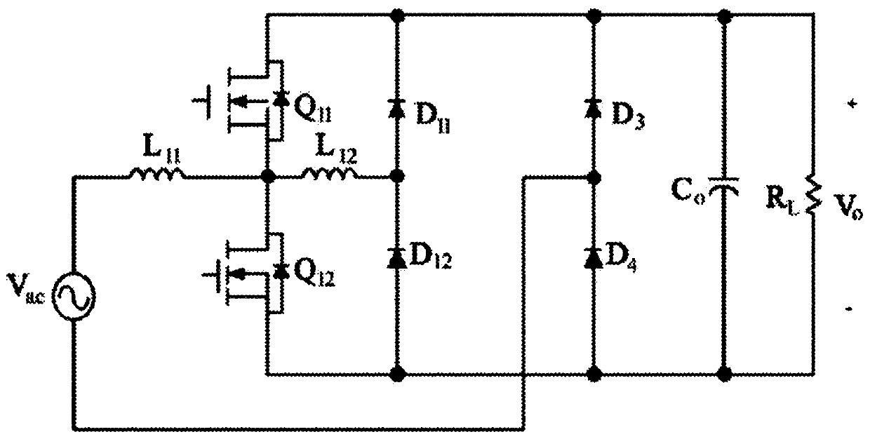
no. 3 example
[0080] The circuit principle diagram of the bridgeless PFC switching power supply circuit of the third embodiment of the present invention is as follows Figure 16As shown, the diode is used as the current blocker as in the second embodiment, and the only difference from the second embodiment is that the positions of the switch tube and the current blocker are interchanged. A bridgeless PFC switching power supply circuit, comprising: an AC input source AC, a first inductance L1 and a second inductance L2, the first end of the first inductance L1 is connected to the first end of the AC input source AC, and the first end of the second inductance L2 One end is connected to the second end of the AC input source AC; including: the first diode D1 and the second diode D2, the third diode D3 and the fourth diode D4, the second end of the first inductor L1 The anode of the first diode D1 is connected to the anode of the third diode D3, and the second end of the second inductance L2 is ...
PUM
 Abstract
Description
Claims
Application Information