
Data acquisition device for safety monitoring

A data acquisition and safety monitoring technology, applied in the direction of measuring devices, signal transmission systems, instruments, etc., can solve the problems of equipment unable to work for a long time, single communication mode, single function, etc., to achieve effective automatic data collection and monitoring, improve management efficiency, The effect of stable and reliable transmission

Pending Publication Date: 2020-06-05
湖南北斗微芯产业发展有限公司 +1
View PDF0 Cites 1 Cited by
  • Summary
  • Abstract
  • Description
  • Claims
  • Application Information

AI Technical Summary

Problems solved by technology

[0003] In the existing technology, the function of the data acquisition device is simplistic, the interface of data acquisition is relatively small, and only a limited number of sensors can be connected; in the data communication between the device and the server, the communication method is single, generally using cellular network communication or Ethernet In this way, the equipment works in a harsh field environment. Once the communication signal is interrupted by the environment, the sensor data will not be transmitted back to the server; the device lacks the data analysis capability of the sensor, and will not transmit the data in time when the monitoring object is abnormal. to the server; in many monitoring environments, it is generally not possible to use the mains power supply, and can only use the combination of solar energy and batteries for power supply. Many data acquisition and transmission devices have the disadvantage of high power consumption, which makes the equipment unable to work for a long time and increases the cost of remote monitoring. cost

Method used


Image

  • Data acquisition device for safety monitoring
  • Data acquisition device for safety monitoring
  • Data acquisition device for safety monitoring

Examples


Embodiment Construction

[0020] In order to enable those skilled in the art to better understand the technical solutions in this specification, the technical solutions in this specification will be clearly and completely described below in conjunction with the accompanying drawings in this specification.

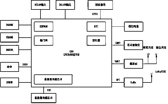
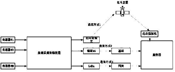
[0021] figure 1 It describes the hardware system structure diagram of the data acquisition device for safety monitoring. NXP LPC54606J512 is used as the main control unit of the entire device to realize the control and system management of the entire peripheral module. The internal storage of the main control unit is used to store configuration parameters, and the watchdog is used to prevent the software system from running away; the internal RTC provides time parameters for the system, which are used for data storage and adding time stamp information to data transmission frames. RTC provides two Power supply mode, in the case of external power supply of the device, the RTC power supply is converted...


PUM


Abstract

The invention discloses a data acquisition device for safety monitoring, and relates to the technical field of safety monitoring, in particular to a data acquisition device for safety monitoring. Theinvention discloses a data acquisition device for safety monitoring. The device comprises a data acquisition module, a data communication module, a data storage module, a temperature and humidity module, a clock module, a state indication module and a positioning module. According to the device, real-time data acquisition of multiple sensors can be realized, multiple communication links are provided to transmit data to a server, and the data can be acquired and transmitted to the server in a triggering manner under the condition that the sensor data is abnormal; the device can locally store the collected original data, and even if a communication link fails, it is ensured that the data is not lost; the device provides a positioning function, so that the device is effectively prevented frombeing stolen; and the device can automatically enter a low-power-consumption management mode under the condition of low electric quantity. The device not only reduces the use cost, but also ensures that the data is safe and not lost, and is mainly used for safety monitoring.

Description

technical field [0001] The invention relates to the technical field of safety monitoring, in particular to a data acquisition device for safety monitoring. Background technique [0002] With the development of science and technology, online safety monitoring of the environment has attracted everyone's attention. In engineering projects, when monitoring stress, rainfall, moisture content, displacement and other monitoring objects, various sensors need to be used, and the data acquisition device is the key equipment for users to obtain sensor data in real time. [0003] In the existing technology, the function of the data acquisition device is simplistic, the interface of data acquisition is relatively small, and only a limited number of sensors can be connected; in the data communication between the device and the server, the communication method is single, generally using cellular network communication or Ethernet In this way, the equipment works in a harsh field environmen...

Claims


Application Information

Patent Timeline
Patent Type & Authority Applications(China)
IPC IPC(8): H04L29/08G08C17/02G01D21/02
CPCG08C17/02H04B1/40G01D21/02H04L67/025
Inventor 杨世忠甘雨
Owner 湖南北斗微芯产业发展有限公司
Learn More