
Vacuum heat-preservation continuous distillation gas-liquid separator

A technology of vacuum heat preservation and liquid separator, which is applied in the direction of steam condensation, separation methods, instruments, etc., can solve the problems of physical injury of testers, pollution of laboratory environment, low work efficiency, etc. damage, simple device structure, and the effect of improving work efficiency

Pending Publication Date: 2020-06-09
NANJING UNIV OF TECH
View PDF2 Cites 0 Cited by
  • Summary
  • Abstract
  • Description
  • Claims
  • Application Information

AI Technical Summary

Problems solved by technology

Most of the volatile phenols, cyanides, sulfides and ammonia nitrogen compounds are poisonous and harmful. During the sample pretreatment process of environmental water quality testing, because the sample is easily escaped from the device during the distillation and absorption process, it not only causes analysis errors, but also pollutes The laboratory environment will cause harm to the body of the tester, so the airtightness of the device must be ensured at all times during the distillation process
The traditional distillation device is composed of a distillation bottle and a condenser tube. The sample is added in an open state, and then heated for distillation and condensation after being sealed. However, some extremely volatile components will be lost in an open state, and the first sample needs to be distilled after the end of distillation. Rinsing and re-sampling of the device does not allow continuous processing of the next sample
The condensing tube of the traditional distillation device is a device that uses the principle of heat exchange to cool and condense the volatile gas components into a liquid. It is difficult to completely ensure the tightness of the device during the distillation process. The tightness is poor, resulting in analysis errors. It pollutes the laboratory environment and causes physical harm to the testers, and the traditional distillation device cannot perform continuous sample injection and continuous distillation, which consumes time, energy, and low work efficiency, which increases the burden on the experimenters

Method used

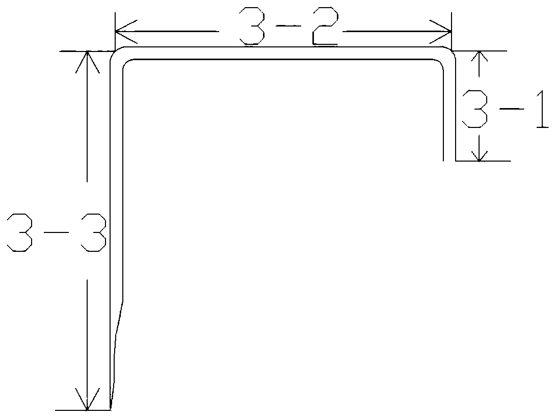

Image

  • Vacuum heat-preservation continuous distillation gas-liquid separator
  • Vacuum heat-preservation continuous distillation gas-liquid separator

Examples


Embodiment 1

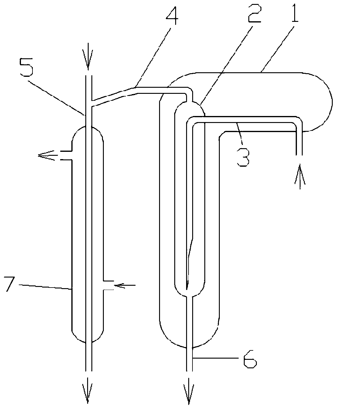
[0027] Such as figure 1 , comprising a vacuum insulation cover 1 and a condenser tube 7, the inside of the vacuum insulation cover 1 is provided with a gas-liquid separation chamber 2 and a guide tube 3; one end of the guide tube 3 extends out of the vacuum insulation cover 1 and is connected to a distillation device for high-temperature steam , the other end extends to the bottom of the gas-liquid separation chamber 2, the gas-liquid separation chamber 2 is longitudinally arranged inside the vacuum insulation cover 1, the bottom end of the gas-liquid separation chamber 2 is connected to the waste liquid drainage tube 6, and the end of the waste liquid drainage tube 6 protrudes In the vacuum insulation cover 1, part of the condensate flows out through the waste liquid drainage pipe 6; the top of the gas-liquid separation chamber 2 is connected to the upper end of the condensation pipe 7 through the air guide pipe 4, and the lower end of the condensation pipe 7 is connected to t...

Embodiment 2

[0034] Such as figure 1 , comprising a vacuum insulation cover 1 and a condenser tube 7, the inside of the vacuum insulation cover 1 is provided with a gas-liquid separation chamber 2 and a guide tube 3; one end of the guide tube 3 extends out of the vacuum insulation cover 1 and is connected to a distillation device for high-temperature steam , the other end extends to the bottom of the gas-liquid separation chamber 2, the gas-liquid separation chamber 2 is longitudinally arranged inside the vacuum insulation cover 1, the bottom end of the gas-liquid separation chamber 2 is connected to the waste liquid drainage tube 6, and the end of the waste liquid drainage tube 6 protrudes In the vacuum insulation cover 1, part of the condensate flows out through the waste liquid drainage pipe 6; the top of the gas-liquid separation chamber 2 is connected to the upper end of the condensation pipe 7 through the air guide pipe 4, and the lower end of the condensation pipe 7 is connected to t...


PUM

PropertyMeasurementUnit
lengthaaaaaaaaaa
lengthaaaaaaaaaa
lengthaaaaaaaaaa

Abstract

The invention discloses a vacuum heat preservation continuous distillation gas-liquid separator, which comprises a vacuum heat preservation cover and a condenser pipe, and a gas-liquid separation cavity and a flow guide pipe are arranged in a vacuum heat preservation cover; one end of the flow guide pipe extends out of the vacuum heat preservation cover to be connected to a high-temperature steamdistillation device, the other end of the flow guide pipe extends to the bottom of the gas-liquid separation cavity, the gas-liquid separation cavity is longitudinally formed in the vacuum heat preservation cover, the bottom end of the gas-liquid separation cavity is connected with a waste liquid drainage pipe, and the tail end of the waste liquid drainage pipe extends out of the vacuum heat preservation cover. The top end of the gas-liquid separation cavity is connected to the upper end of the condenser pipe through a gas guide pipe. The separator disclosed by the invention is carried out ina whole-course closed state, does not need to open the device, and can be used for continuously carrying out gas-liquid separation and absorption, reaction and delivery measurement of volatile components to be detected on distillates of a plurality of samples, so that the working efficiency is effectively improved, and continuous sample injection and gas-liquid separation are realized.

Description

technical field [0001] The invention relates to the technical field of environmental detection, and more specifically relates to a device for on-line distillation and gas-liquid separation of low-boiling substances such as volatile phenols, sulfides, cyanides and ammonia nitrogen. Background technique [0002] Indicators such as volatile phenols, sulfides, cyanides, and ammonia nitrogen are basic testing items for water environment quality standards and comprehensive discharge standards for domestic sewage and industrial wastewater. The detection of these items requires a large amount of samples and high work intensity in the daily detection of environmental protection water quality, and a special distillation device is required for sample pretreatment. Most of the volatile phenols, cyanides, sulfides and ammonia nitrogen compounds are poisonous and harmful. During the sample pretreatment process of environmental water quality testing, because the sample is easily escaped fr...

Claims


Application Information

Patent Timeline
Patent Type & Authority Applications(China)
IPC IPC(8): B01D3/14B01D5/00C02F1/04G01N1/40
CPCB01D3/14B01D5/00C02F1/04G01N1/4022G01N2001/4033
Inventor 陈国松吴冬阳张红漫张之翼石成成黄招霞唐美华李金宽
Owner NANJING UNIV OF TECH
Learn More