
Glass curtain wall manufacturing equipment based on connecting shaft system

A glass curtain wall, connecting shaft technology, applied in metal processing equipment, grinding/polishing equipment, control of workpiece feed movement, etc., can solve the problems of wasting materials, affecting service life, and increasing equipment energy consumption.

Inactive Publication Date: 2020-06-09
刘怡
View PDF6 Cites 2 Cited by
  • Summary
  • Abstract
  • Description
  • Claims
  • Application Information

AI Technical Summary

Problems solved by technology

[0003] Since glass is a silicon crystal product, its own hardness is high and its texture is relatively brittle. During the process of cutting and transferring it, there will be a possibility of cracks inside it, which will affect its later service life. Therefore, the existing technology will The quality inspection of the finished glass curtain wall is carried out, but the waste products detected at this time have no chance to be saved, and can only be crushed and recast, which wastes materials and increases the energy consumption of equipment work. Therefore, a shaft-based Systematic glass curtain wall production equipment came into being

Method used


Image

  • Glass curtain wall manufacturing equipment based on connecting shaft system
  • Glass curtain wall manufacturing equipment based on connecting shaft system
  • Glass curtain wall manufacturing equipment based on connecting shaft system

Examples


Embodiment Construction

[0022] The following will clearly and completely describe the technical solutions in the embodiments of the present invention with reference to the accompanying drawings in the embodiments of the present invention. Obviously, the described embodiments are only some, not all, embodiments of the present invention. Based on the embodiments of the present invention, all other embodiments obtained by persons of ordinary skill in the art without making creative efforts belong to the protection scope of the present invention.

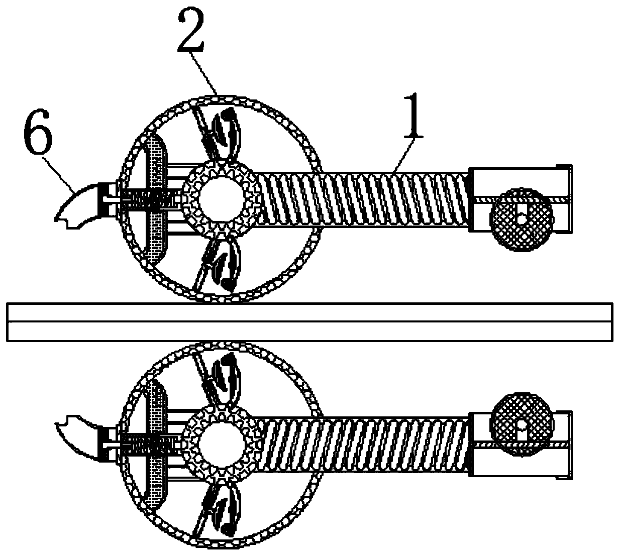
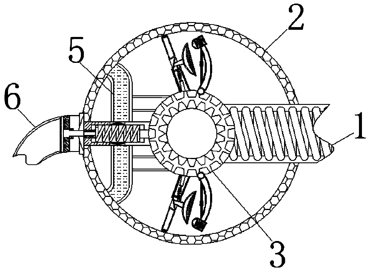
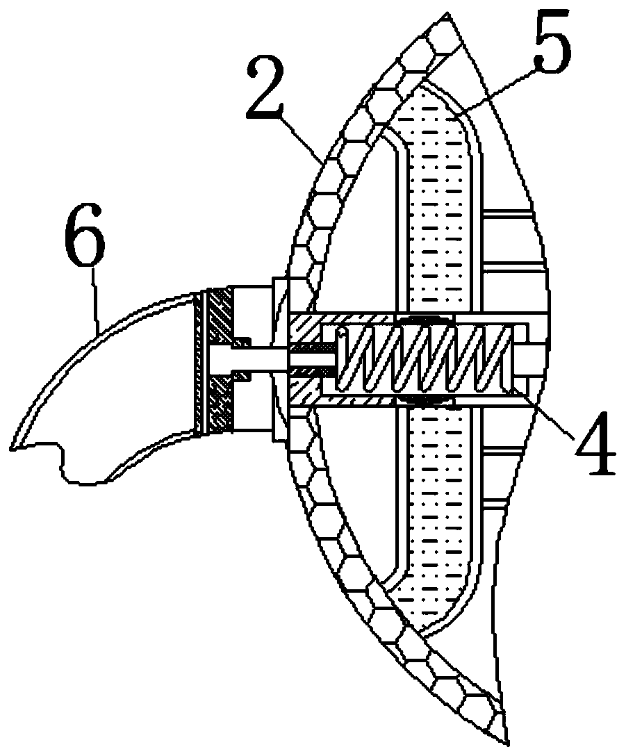
[0023] see Figure 1-5 , a glass curtain wall production equipment based on the coupling system, including a rotating shaft 1, the right end of the rotating shaft 1 is movably connected with a cutting piece, the inside of the cutting piece is movably connected with a frosted disc, the hardness of the frosted disc is much greater than that of glass, and the surface is fixedly connected with a Diamond, the left end of the rotating shaft 1 is movably connected wi...


PUM


Abstract

The invention relates to the technical field of glass curtain wall manufacturing raw material detection, and discloses glass curtain wall manufacturing equipment based on a connecting shaft system. The equipment comprises rotating shafts, the left ends of the rotating shafts are movably connected with detection rings, the interiors of the detection rings are movably connected with gears, the interiors of the gears are movably connected with elastic shafts, the surfaces of the elastic shafts are movably connected with capsules, the ends, away from the gears, of the elastic shafts are movably connected with flowing grooves, the surfaces of the gears are movably connected with swing rods, the surfaces of the swing rods are fixedly connected with sliding rails, the surfaces of the sliding rails are slidably connected with balancing weights, and the ends, away from the gears, of the swing rods are fixedly connected with hammerheads. Thus, the function of pushing glass for cutting is achieved, meanwhile, the swing rods are influenced by the gravitational potential energy of the balancing weights, when the hammerheads make contact with bearing plates, flexible blocks extrude the detectionrings to generate deformation, then the deformation acts on the surface of the glass, and therefore the effect that the physical performance of the glass is detected while the glass is cut is achieved.

Description

technical field [0001] The invention relates to the technical field of glass curtain wall production raw material detection, in particular to a glass curtain wall production equipment based on a coupling system. Background technique [0002] Glass curtain wall refers to the building envelope or decorative structure whose supporting structure system can have a certain displacement capacity relative to the main structure and does not share the effect of the main structure; there are two types of walls: single-layer glass and double-layer glass, and glass curtain wall The production process is: raw material selection, size cutting, gluing edge banding, finished product inspection and so on. [0003] Since glass is a silicon crystal product, its own hardness is high and its texture is relatively brittle. During the process of cutting and transferring it, there will be a possibility of cracks inside it, which will affect its later service life. Therefore, the existing technology ...

Claims


Application Information

Patent Timeline
IPC IPC(8): B24B27/06B24B55/00B24B49/00G01N3/40B05C5/02
CPCB05C5/02B24B27/06B24B27/0683B24B49/00B24B55/00G01N3/40G01N2203/0019G01N2203/0039
Inventor 刘怡杜江何北北
Owner 刘怡
Learn More