Narrow flow channel turbine

A narrow channel and turbine technology, applied in the field of narrow channel turbines, can solve problems such as prone to surge, high pressure ratio of centrifugal compressors, increased energy consumption, etc., to achieve the effects of broadening applications, improving efficiency, and reducing energy consumption

Inactive Publication Date: 2020-06-09
时剑
View PDF0 Cites 0 Cited by
  • Summary
  • Abstract
  • Description
  • Claims
  • Application Information

AI Technical Summary

Problems solved by technology

[0003] Existing impeller-type fluid delivery mechanisms such as centrifugal pumps have low efficiency under the condition of small flow and high head, and at the same time, cavitation is easy to occur at high speed. Surge
Therefore, the use of the impeller type fluid conveying mechanism is limited, and the energy consumption is increased.

Method used


Image

  • Narrow flow channel turbine
  • Narrow flow channel turbine

Examples


Embodiment Construction

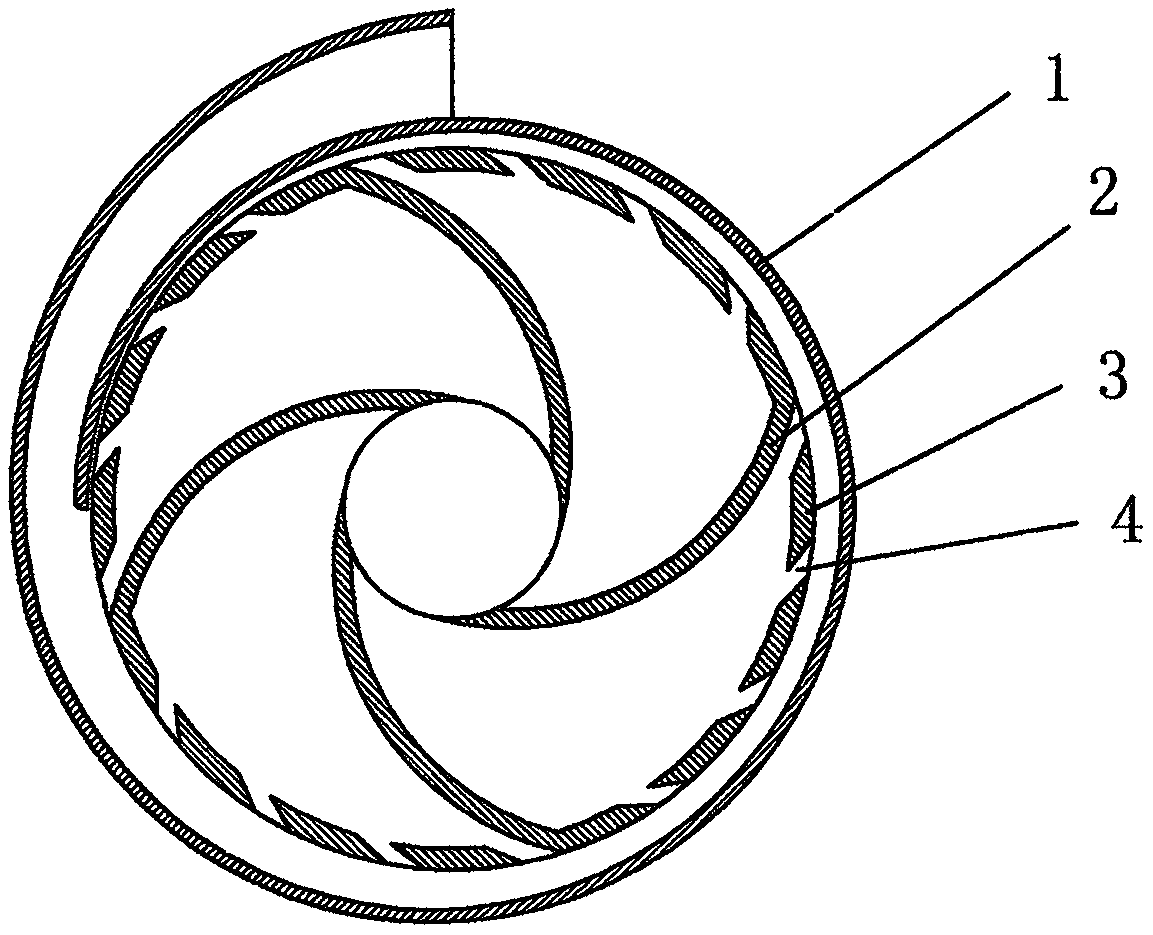
[0009] In the figure, there is a turbine rotor (2) inside the casing (1), and a closed retaining wall (3) is arranged on the circumference of the turbine rotor (2), and small holes (4) are distributed on the closed retaining wall (3).

[0010] When working, the turbine rotor (2) is driven by external force to rotate at a high speed, the fluid is sucked in from the middle of the turbine rotor (2), and then sprayed into the casing (1) through the small hole (4).

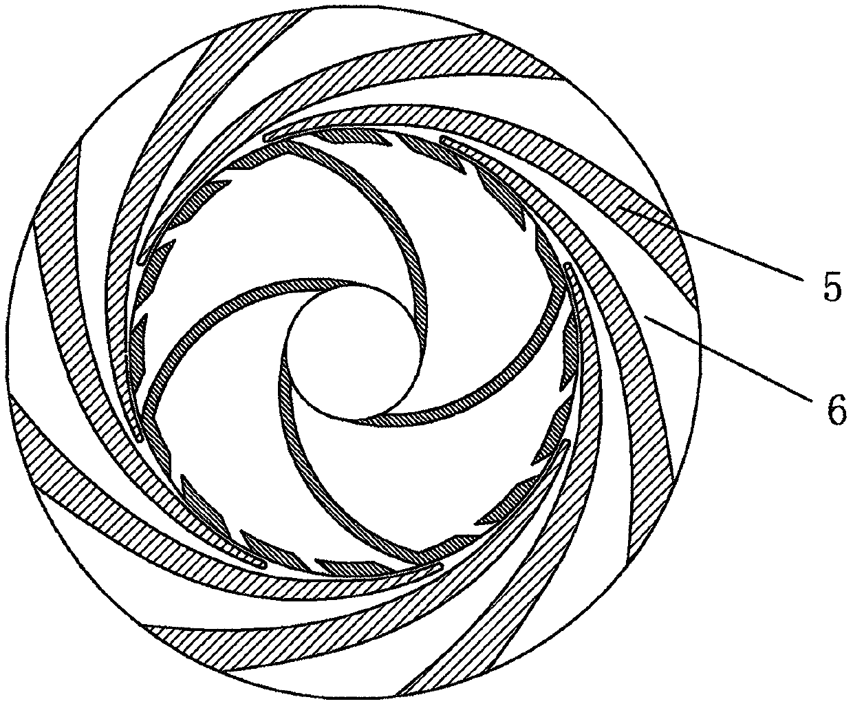
[0011] attached figure 2 It is a schematic diagram of a narrow-channel turbine rotor coupled with a narrow-channel diffuser mechanism. The diffuser (5) is provided with a plurality of curved narrow-channel diffuser slots (6). Due to the bending, the flow becomes longer, so the diffuser is more efficient. full.

[0012] The present invention does not limit the shape of the casing (1), which may be a volute, a pipeline or a pressure vessel, etc., all of which are within the protection scope of the present invention.


PUM


Abstract

The invention provides a narrow flow channel turbine. The narrow flow channel turbine comprises a shell and a turbine rotor, wherein a sealing retaining wall is arranged on the circumference of the turbine rotor, and small holes are distributed in the sealing retaining wall, so that fluid sucked by the turbine rotor at high rotating speed is sealed in the rotor; and the fluid is compressed and filled in the radial direction under the action of centrifugal force, cavitation or surge is avoided, and the fluid is sprayed into the shell only through the small holes, so that high lift under small flow is achieved. The efficiency of a centrifugal pump can be improved under the working condition of the small flow and the high lift, and meanwhile, the cavitation is not generated at high speed so that the centrifugal compressor can reach the high pressure ratio at the small flow, and meanwhile, the surge is not generated at the high speed; and the application range of an impeller type fluid conveying mechanism is widened, and energy consumption is reduced.

Description

[0001] Technical field [0002] The invention relates to a narrow channel turbine, which belongs to the technical field of fluid machinery. Background technique [0003] Existing impeller-type fluid delivery mechanisms such as centrifugal pumps have low efficiency under the condition of small flow and high head, and at the same time, cavitation is easy to occur at high speed. Surge. Therefore, the use of the impeller type fluid conveying mechanism is limited, and the energy consumption is increased. Contents of the invention [0004] In order to overcome the deficiencies in the prior art, the present invention provides a narrow-channel turbine, which includes a casing and a turbine rotor, a closed retaining wall is arranged on the circumference of the turbine rotor, and small holes are distributed on the closed retaining wall In this way, the fluid sucked by the turbine rotor at high speed is sealed in the rotor, and the fluid is radially compressed and enriched under the ...

Claims


Application Information

Patent Timeline
Patent Type & Authority Applications(China)
IPC IPC(8): F04D29/22F04D29/66F04D29/28
CPCF04D29/22F04D29/284F04D29/666F04D29/669
Inventor 时剑
Owner 时剑
Why Eureka
Try Eureka