LED filament lamp
A LED filament lamp and LED filament technology, applied in lighting devices, cooling/heating devices of lighting devices, light sources, etc., can solve the problems of insufficient luminous flux and can only be used as decorative lights, etc., to shorten the vertical distance and reduce the speed of light decay , the effect of increasing the diameter of the spiral
- Summary
- Abstract
- Description
- Claims
- Application Information
AI Technical Summary
Problems solved by technology
Method used
Image

Examples
Embodiment 1
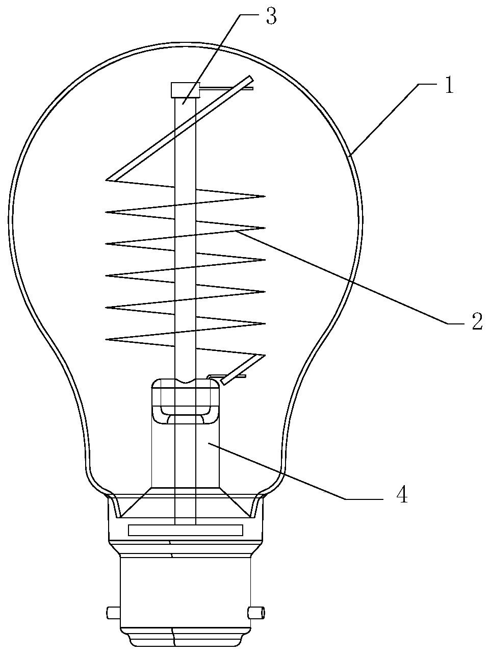
[0036] refer to figure 1 , an LED filament lamp, comprising: a bulb 1, a flexible LED filament module, a rotating device 3, a flexible LED filament module and a supporting device 4 of the rotating device 3;
[0037] The flexible LED filament module includes at least one helical flexible LED filament 2, the first end of the flexible LED filament 2 is connected to the supporting device 4, and the second end is connected to the rotating device 3;
[0038] The rotation of the rotating device 3 drives the number of helical turns of the flexible LED filament 2 to change, and at the same time, the diameter of the helix also changes. Therefore, when the flexible LED filament 2 is turned on, the number of turns of the flexible LED filament 2 can be changed, and the diameter of the flexible LED filament 2 can be changed at the same time. This makes the shape of the flexible LED filament module changeable. It can also be set that when the flexible LED filament 2 is turned on, the helic...
Embodiment 2
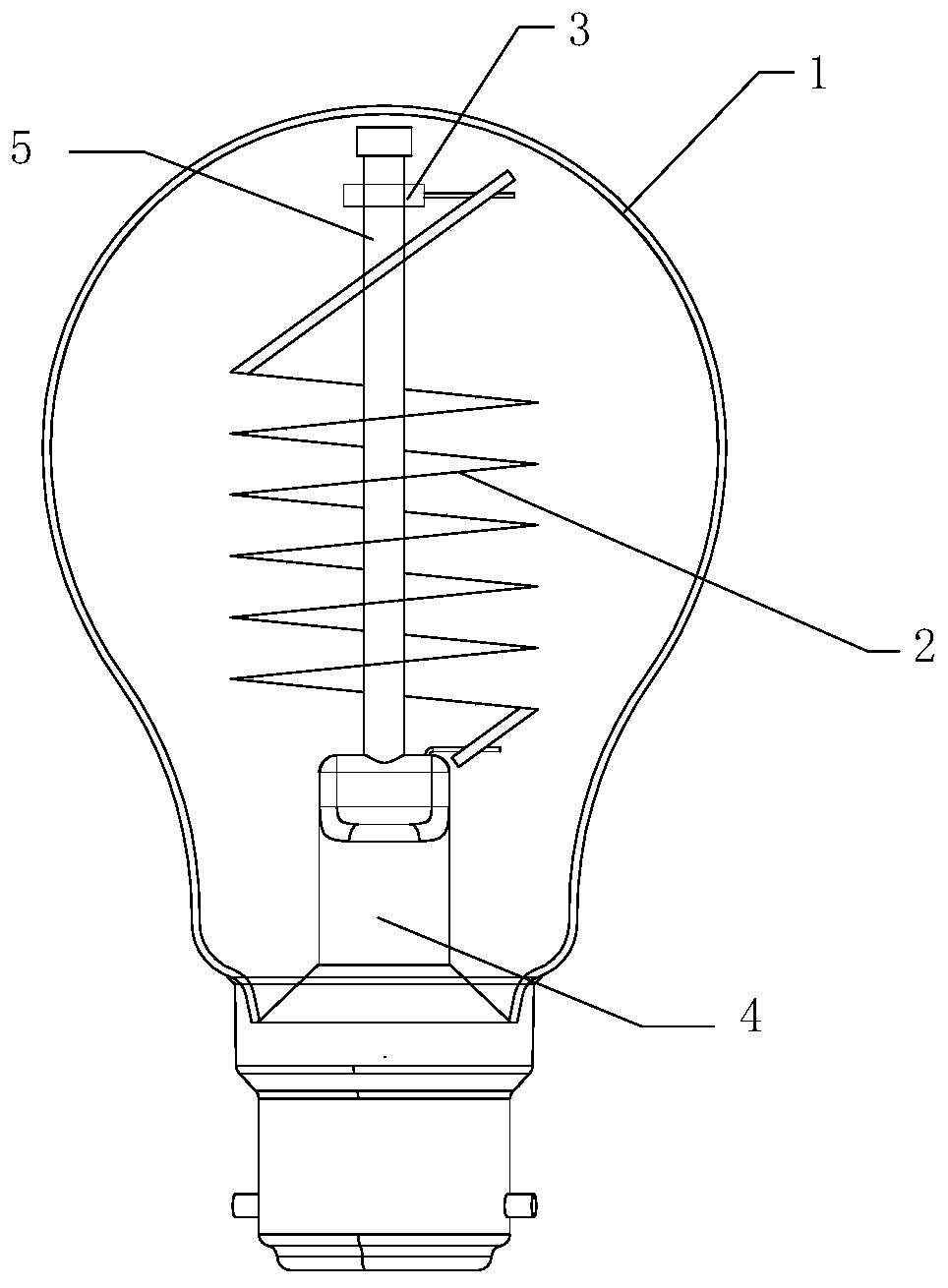
[0042] refer to figure 2 , in this embodiment, in order to realize the rotation of the rotating device 3, it also includes a stem 5 extending axially along the bulb 1; the lower end of the stem 5 along the axial direction is fixed to the supporting device 4;
[0043] The rotating device 3 is sheathed on the stem 5 ; the rotating device 3 rotates around the axial direction of the stem 5 while moving along the axial direction of the stem 5 . That is to say, through the cooperation between the rotating device 3 and the stem 5 , the translation of the rotating device 3 along the axis of the stem 5 is reversed to the rotation around the axis of the stem 5 .
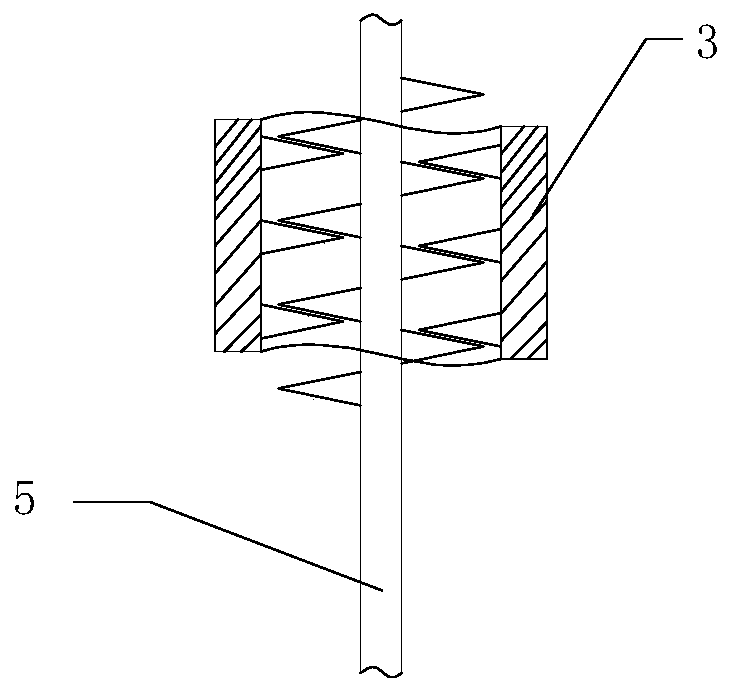
[0044] In order to achieve the above effects, the rotating device 3 and the stem 5 are connected by threads. Specifically, the inner diameter or inner thread of the rotating device 3 matches the outer thread of the stem 5, such as image 3 shown.
[0045] Therefore, when the rotating device 3 is subjected to external force...
Embodiment 3
[0049] refer to Figure 5 , in this embodiment: in order to realize the rotation of the rotating device 3, it also includes a stem 5 extending axially along the bulb 1; the lower end of the stem 5 along the axial direction is fixed to the supporting device 4; it also includes a A telescopic device 6 that drives the rotating device 3 to rotate; one end of the telescopic device 6 is sleeved outside the stem 5 and abuts against the rotating device 3, and the other end passes through the supporting device 4 and is connected to the drive circuit;
[0050] In order to achieve the above effects, the rotating device 3 and the stem 5 are connected by threads. Specifically, the inner diameter or inner thread of the rotating device 3 matches the outer thread of the stem 5, such as Figure 6 shown.
[0051] The telescoping device 6 drives the rotating device 3 to move along the axial direction of the stem, and the rotating device 3 rotates around the axial direction of the stem 5 while ...
PUM
 Abstract
Description
Claims
Application Information
 - R&D
- Intellectual Property
- Life Sciences
- Materials
- Tech Scout
- Unparalleled Data Quality
- Higher Quality Content
- 60% Fewer Hallucinations
Browse by: Latest US Patents, China's latest patents, Technical Efficacy Thesaurus, Application Domain, Technology Topic, Popular Technical Reports.
© 2025 PatSnap. All rights reserved.Legal|Privacy policy|Modern Slavery Act Transparency Statement|Sitemap|About US| Contact US: help@patsnap.com