Heat exchanger

A heat exchanger and heat exchange core technology, applied in the direction of indirect heat exchanger, heat exchanger shell, heat exchanger type, etc., can solve the problem of high working pressure of air conditioning system, immature component design, and lack of mass application of the system, etc. question

Active Publication Date: 2020-06-09
ZHEJIANG SANHUA AUTOMOTIVE COMPONENTS CO LTD
View PDF3 Cites 2 Cited by
  • Summary
  • Abstract
  • Description
  • Claims
  • Application Information

AI Technical Summary

Problems solved by technology

However, the working pressure of this type of air conditioning system is very high. When designing the CO2 heat exchange device, this feature of this type of system needs to be fully considered. Due to the immature design of its components, this type of system has not been widely used
[0004]Generally speaking, CO2 heat exchangers mainly include tube-fin type, micro-channel

Method used


Image

  • Heat exchanger
  • Heat exchanger
  • Heat exchanger

Examples


Embodiment Construction

[0023] In order to enable those skilled in the art to better understand the solution of the present invention, the present invention will be further described in detail below in conjunction with the accompanying drawings and specific embodiments.

[0024] In this article, terms such as "front, back, left, and right" are established based on the positional relationship shown in the drawings. Depending on the drawings, the corresponding positional relationship may also change accordingly. It is understood as an absolute limitation on the scope of protection; moreover, relative terms such as "first" and "second" are only used to distinguish one from another component with the same name, and do not necessarily require or No such actual relationship or order between these components is implied.

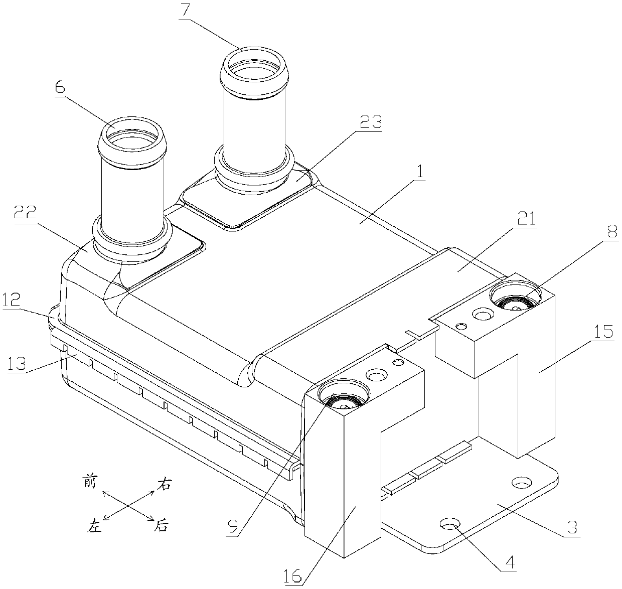
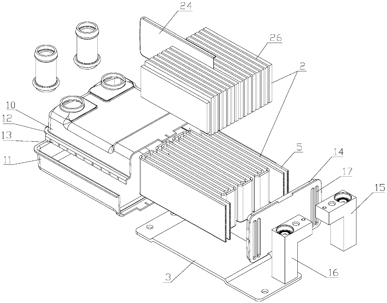
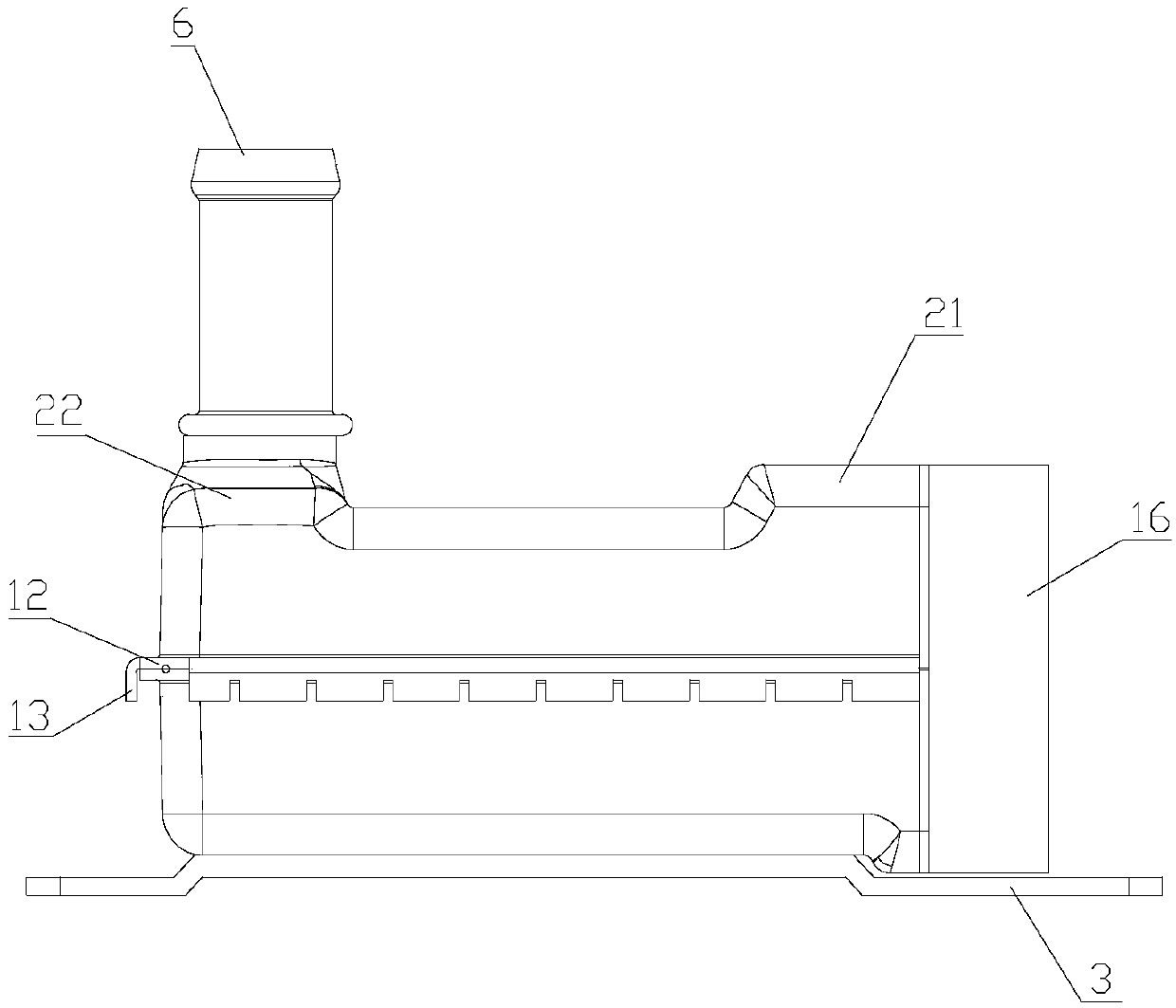
[0025] Please refer to figure 1 , figure 2 , image 3 , figure 1 It is an axonometric view of a heat exchanger disclosed in an embodiment of the present invention; figure 2 for fig...


PUM


Abstract

The invention discloses a heat exchanger. The heat exchanger comprises a housing and a heat exchange core body, wherein the heat exchange core body comprises a flat tube with a refrigerant runner therein; the flat tube is provided with a plurality of flat parts which are parallel to each other and bending parts for connecting adjacent two flat parts in a transitional mode; at least one part of each flat tube is positioned inside the housing; a cooling liquid runner is formed inside the housing; the part of the cooling liquid runner of the housing is divided into at least two cooling liquid flow paths which are arranged side by side in a direction parallel to the flat parts of the flat tube, and flow directions of the adjacent two cooling liquid flow paths are reverse; the portion, at a turning position of the adjacent two cooling liquid flow paths, of the housing is provided with a hollow bulged part, and the bulged part is positioned above or below the turning position of the flat tube; and an inner cavity of the bulged part communicates with the adjacent two cooling liquid flow paths with reverse two directions. The heat exchanger disclosed by the invention can prolong the cooling liquid flow paths, improves heat exchange efficiency, and is relatively high in pressure bearing capacity.

Description

technical field [0001] The invention relates to the technical field of heat exchange devices, in particular to a CO 2 Refrigerant heat exchanger. Background technique [0002] CO 2 It is a new type of environmentally friendly refrigerant, which can reduce the global greenhouse effect and solve the problem of environmental pollution caused by compounds. It has good economy and practicability. [0003] with CO 2 The compression refrigeration cycle system as the working medium can be used in most refrigeration and heating fields. However, the working pressure of this type of air-conditioning system is very high. When designing the CO2 heat exchange device, this feature of this type of system needs to be fully considered. Due to the immature design of its components, this type of system has not been widely used. [0004] Generally speaking, CO 2 Heat exchangers mainly include tube-fin type, micro-channel, plate type, casing type and shell-and-tube type. Traditional CO2 micr...

Claims


Application Information

Patent Timeline
IPC IPC(8): F25B39/00F28D7/00F28F1/02F28F9/26
CPCF25B39/00F28D7/00F28F1/022F28F9/26
Inventor 不公告发明人
Owner ZHEJIANG SANHUA AUTOMOTIVE COMPONENTS CO LTD
Why Eureka
Try Eureka