
Device and method for testing plume smoke particles of solid rocket engine

A technology of solid rockets and testing devices, which is applied in the field of aerospace power and can solve problems such as large errors, strong radiation, and high temperatures

Pending Publication Date: 2020-06-09
UNIV OF SHANGHAI FOR SCI & TECH +1
View PDF0 Cites 4 Cited by
  • Summary
  • Abstract
  • Description
  • Claims
  • Application Information

AI Technical Summary

Problems solved by technology

However, the particle size of these plume particle parameters has multiple orders of magnitude (from nanometers to millimeters), the particle concentration also has a large range, and the temperature is high and the radiation is strong, which brings great challenges to the measurement of plume particle parameters. At present, the collection method is mainly used to obtain engine plume particles, but the efficiency of collecting particles by this method is limited, and the cold state test after collection has a large error compared with the real high temperature state. At present, there is no effective online test method to evaluate solid rockets Parameters of engine plume smoke particles

Method used


Image

  • Device and method for testing plume smoke particles of solid rocket engine
  • Device and method for testing plume smoke particles of solid rocket engine
  • Device and method for testing plume smoke particles of solid rocket engine

Examples


Embodiment

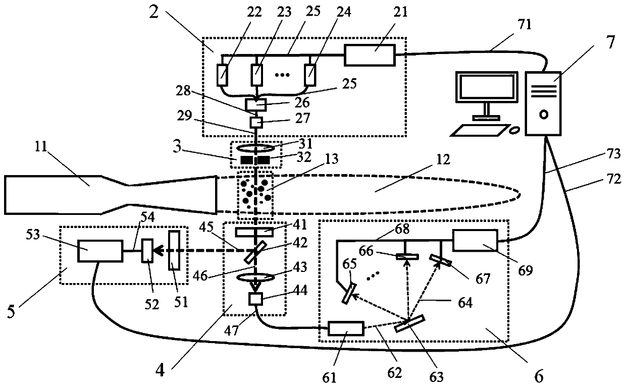
[0056] like figure 1 As shown, the present embodiment provides a solid rocket motor plume smoke particle testing device, which includes a laser light source part 2, a laser modulation part 3, a laser receiving part 4, a laser diffraction detection part 5, a laser attenuation detection part 6, Particle test processing unit 7 , cables 71 , 72 , 73 and optical fibers 28 , 26 , 47 .

[0057] The solid rocket motor plume smoke particle test device is used for testing the solid rocket motor plume smoke particles, and is arranged in the areas on both sides of the exhaust plume 12 of the engine to be tested 11 .

[0058] Wherein, the laser light source part 2 is located on the side of the engine plume 12 and is used to generate incident laser light 20 with different wavelengths.

[0059] The laser modulation unit 3 is located between the engine plume 12 and the laser light source unit 2, and is used to receive the incident laser light 20 emitted by the laser light source unit 2, and ...


PUM


Abstract

The invention discloses a device and method for testing plume smoke particles of a solid rocket engine. The device comprises a laser modulation part, a laser receiving part, a laser diffraction detection part, a laser attenuation detection part and a particle test processing part. The laser modulation part is located between an engine plume and a laser light source part and used for modulating thespot size, the beam expanding angle, the effective irradiating measurement area and other laser space parameters of incident laser. The laser receiving part is located on the other side of the engineplume, and the laser receiving part is used for gathering and receiving transmission lasers with different wavelengths after passing through a plume to be measured and splitting the transmission lasers into a first light beam and a second light beam through a semi-transparent and semi-reflective mirror. The laser diffraction detection part receives the first light beam and is used for detecting the diffraction light energy distribution of the first light beam. The laser attenuation detection part receives the second light beam, irradiates a grating and then splits the second light beam into aplurality of split lasers according to the wavelength. The particle test processing part is used for controlling the laser light source part, wherein particle test processing part is respectively incommunication connection with the laser diffraction detection part and the laser attenuation detection part, and is used for processing and displaying plume smoke particle parameters of the solid rocket engine.

Description

technical field [0001] The invention belongs to the technical field of aerospace power, and relates to a solid rocket motor plume smoke particle testing device and method. Background technique [0002] Solid rocket motors are widely used in the field of aerospace power due to their high reliability and good performance. With the rapid development of military and aerospace, there are more and more requirements for solid rocket motors. The development of propellant formulations is no longer a one-sided pursuit of higher energy, but gradually transforms into a comprehensive approach to pursue low characteristic signals while ensuring energy performance. sexual indicators. The exhaust plume of a solid rocket motor is the combustion product discharged from the nozzle at supersonic speed, which will further diffuse and expand at the outlet of the nozzle to form a luminous and hot plume flow field, and its interaction with the surrounding environment will form smoke, radiation , ...

Claims


Application Information

Patent Timeline
Patent Type & Authority Applications(China)
IPC IPC(8): G01M15/14G01N15/00G01N15/02G01N15/06
CPCG01M15/14G01N15/00G01N15/0205G01N15/0211G01N15/06G01N15/075
Inventor 马庆王继王学峰杨斌王勇陈晓龙王志新陈坚于海涛潘科玮张驰诸星辰
Owner UNIV OF SHANGHAI FOR SCI & TECH
Learn More