
Constant volume transformation method test system for gas transmittance

A gas transmission rate and testing system technology, applied in the field of gas permeameter, can solve the problems of complex valve pipeline, no consideration of high pressure data, inability to realize high pressure and high and low temperature settings, etc., to achieve simple and convenient operation and reduce gas leakage. rate, the effect of reducing the number of

Active Publication Date: 2020-06-12
TIANJIN POLYTECHNIC UNIV
View PDF9 Cites 2 Cited by
  • Summary
  • Abstract
  • Description
  • Claims
  • Application Information

AI Technical Summary

Problems solved by technology

In the test method of gas separation membrane material, in 1986, the William Koros group of Georgia Institute of Technology in the United States reported a system based on the constant volume pressure change method to test gas permeation [J.Membr.Sci.1986,29,229-238.], but this The valves and pipelines of the system are complex; domestic patents on gas permeation instruments, such as patents with publication numbers CN209264513 and CN105466831, but none of the above patents can realize high-pressure and high-low temperature settings, and do not consider high-pressure data, especially 20-30 atmospheric pressure or more However, the actual gas separation is often at 20-30 atmospheres or even above 60 atmospheres. High pressure conditions put forward higher requirements for the gas leakage rate of the instrument.
In addition, many gas separations are carried out below room temperature, and there are no reports on the same set of equipment that can test from subzero to high temperature and high pressure.

Method used


Image

  • Constant volume transformation method test system for gas transmittance
  • Constant volume transformation method test system for gas transmittance
  • Constant volume transformation method test system for gas transmittance

Examples


Embodiment Construction

[0023] The following will clearly and completely describe the technical solutions in the embodiments of the present invention with reference to the accompanying drawings in the embodiments of the present invention. Obviously, the described embodiments are only some, not all, embodiments of the present invention. Based on the embodiments of the present invention, all other embodiments obtained by persons of ordinary skill in the art without making creative efforts belong to the protection scope of the present invention.

[0024] The purpose of the present invention is to provide a constant volume variable pressure method test system for gas permeability, so as to solve the problems in the prior art, reduce the air leakage rate of the equipment, and improve the test accuracy and range.

[0025] In order to make the above objects, features and advantages of the present invention more comprehensible, the present invention will be further described in detail below in conjunction wit...


PUM


Abstract

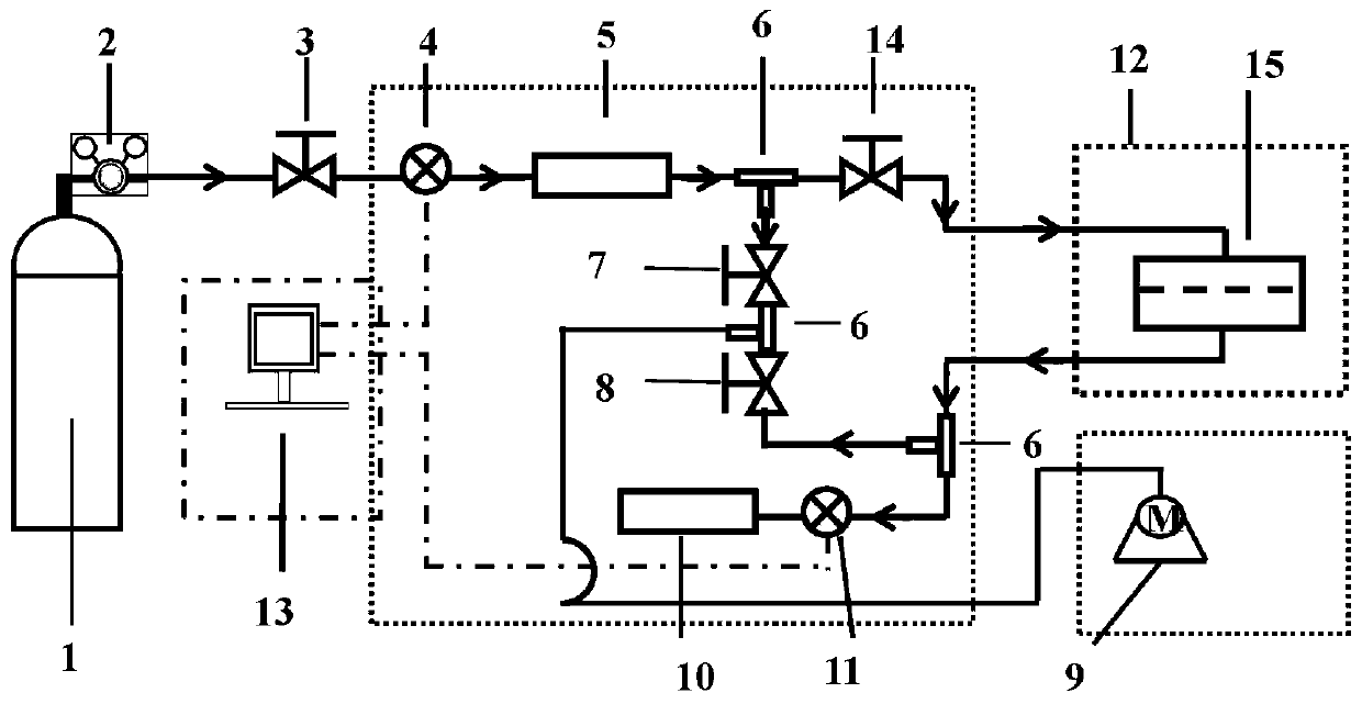
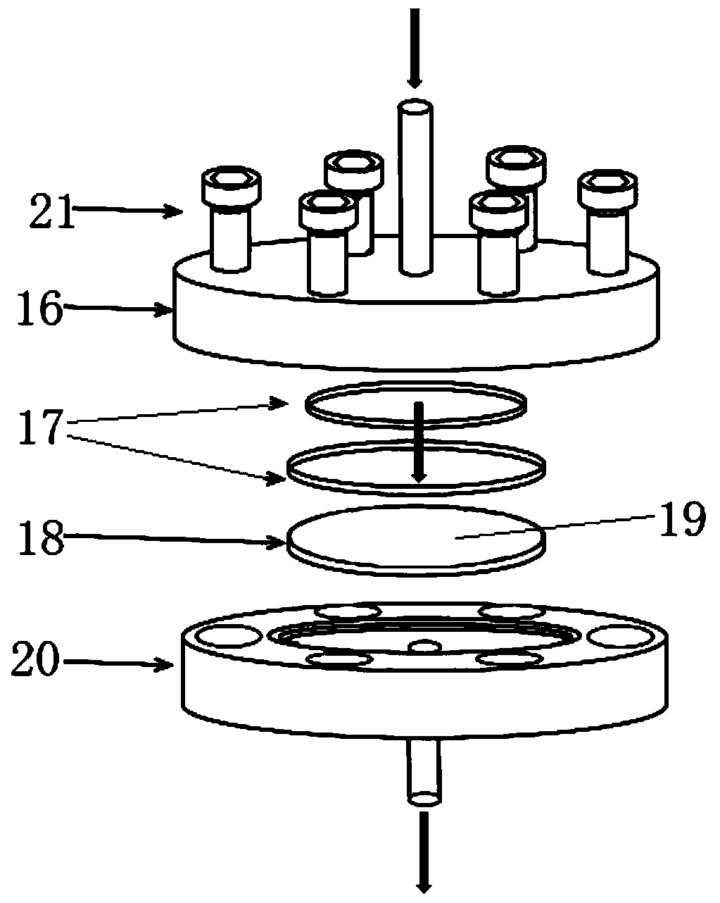
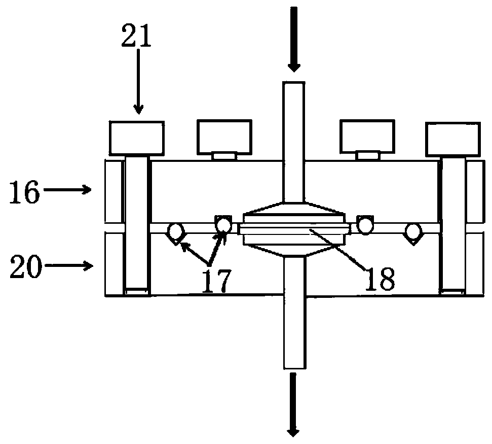
The invention discloses a constant volume transformation method test system for gas transmittance. The system comprises a computer, a data acquisition module, a vacuum pump, a gas cylinder, a pressuretransmitter, an upstream gas storage tank, a downstream gas storage tank, a membrane pool assembly and a pressure sensor, the inlets of the upstream gas storage tank and the downstream air storage tank are respectively provided with a pressure sensor, an upstream vacuumizing valve, a tee joint and a downstream vacuumizing valve are sequentially arranged on a pipeline between the upstream gas storage tank and the downstream gas storage tank, the third end of the tee joint is connected with the vacuum pump, the membrane pool assembly is connected to the pipeline between the upstream gas storagetank and the downstream gas storage tank in parallel, the pressure transmitter, the pressure sensor and the temperature control box are connected with the data acquisition module, and the data acquisition module and the vacuum pump are electrically connected with the computer. The number of valves is reduced, the operation is simple and convenient, the gas leakage rate and error of the test system are greatly reduced, organic glass and aluminum profiles are used as a frame, the weight and size of equipment are reduced, and the cost is reduced.

Description

technical field [0001] The invention relates to the technical field of gas permeation instruments, in particular to a constant volume pressure swing test system for gas permeability. Background technique [0002] Gas separation has a huge market and prospect in the fields of energy saving and emission reduction, green chemical industry, natural gas, biogas purification, hydrogen energy, and biomedicine. The membrane material permeability test system is a test system for studying the intrinsic permeability and selectivity of polymers and other materials to gases, and is an indispensable characterization method for the development of polymer gas separation membrane materials. The gas separation membrane material transmission rate test equipment currently on the market has high air leakage rate, low test accuracy, complicated pipelines, and heavy equipment, which cannot test high and low temperature and high and low pressure at the same time. The accuracy of the results obtain...

Claims


Application Information

Patent Timeline
Patent Type & Authority Applications(China)
IPC IPC(8): B01D65/10
CPCB01D65/102Y02A20/131
Inventor 马小华李凯华朱芷杨
Owner TIANJIN POLYTECHNIC UNIV
Learn More