System and method capable of carrying out flue gas denitration and efficiency increasing through ozone

An ozone and flue gas technology, applied in the field of industrial waste gas purification, environmental protection and energy, can solve the problems of high site requirements, complex fuel, large ammonia escape, etc., and achieve the effects of saving space, ensuring normal use, and saving investment

Inactive Publication Date: 2020-06-12
ZHEJIANG HOPE ENVIRONMENTAL PROTECTION ENG
8 Cites 0 Cited by

AI-Extracted Technical Summary

Problems solved by technology

[0004] The present invention is mainly aimed at rapid load changes of circulating fluidized bed boilers, complex fuels, and NO in flue gas x Due to the characteristics of large concentration changes, the existing SNCR method has low efficiency and cannot deal with NO x In the case of high content, rapid change, and large ammonia escape, ...

Method used

A kind of method that utilizes ozone to carry out flue gas denitrification synergism, comprises the following steps: flue gas comes out from circulating fluidized bed boiler 1, passes through cyclone separator 2, high temperature economizer 3, denitrification catalyst 4, medium/ After the low-temperature economizer 5, it enters the downstream equipment through the flue 6, and utilizes the high oxidation property of ozone to couple SNCR+SCR to improve the denitrification efficiency and meet the super emission requirements of high NOx.
As shown in Figure 1, a kind of system that utilizes ozone to carry out flue gas denitrification synergism, comprises circulating fluidized bed boiler 1 and on-line monitoring system, and the outlet pipe of circulating fluidized bed boiler 1 is connected with cyclone separator 2, The main function of the cyclone separator 2 is to remove the solid particle impurities carried in the flue gas as much as possible. The outlet pipe of the cyclone separator 2 is connected with a flue 6, and the flue 6 is provided with a high-temperature economizer 3 and a denitrification catalyst 4 in sequence. , medium/low temperature economizer 5, an ozone generating system is connected to the outlet pipe of the circulating fluidized bed boiler 1, the ozone generating system can generate ozone and transport the ozone to the outlet pipe of the circulating fluidized bed boiler 1, and cyclone separation The inlet pipe and the outlet pipe of the device 2 are connected with an ammonia water supply system, the ammonia water supply system can produce ammonia water and transport the ammonia water to the inlet and outlet of the cyclone separator 2, and the flue 6 is provided with a device for removing the surface of the denitrification catalyst 4 The soot blowing system with accumulated dust, the setting of the soot blowing system can ensure that the denitrification catalyst 4 plays an effective role. The whole system is controlled by the DCS system. When the whole system is running, the high oxidation of ozone is used to couple the SNCR+SCR method, It can improve the denitrification efficiency to meet the high NOx over-emission requirements, and only needs one layer of denitrification catalyst 4, which is arranged between the high-temperature economizer 3 and the medium/low temperature e...

Abstract

The invention relates to the field of industrial waste gas purifying environment friendliness and energy, in particular to a system and method capable of carrying out flue gas denitration and efficiency increasing through ozone. The system capable of carrying out flue gas denitration and efficiency increasing through the ozone comprises a circulating fluidized bed boiler and an online monitoring system, a gas outlet pipe of the circulating fluidized bed boiler is connected with a cyclone separator, a gas outlet pipe of the cyclone separator is connected with a flue, the flue is internally andsequentially provided with a high-temperature economizer, a denitration catalyst, and a medium/low temperature economizer, an ozone generation system is connected to the gas outlet pipe of the circulating fluidized bed boiler, a gas inlet pipe and the gas outlet pipe of the cyclone separator are connected with ammonium hydroxide supply systems, the flue is provided with an ash blowing system usedfor removing accumulated ash on the surface of the denitration catalyst, SNCR and SCR methods can be coupled, the denitration efficiency can be improved, the NOx ultra-emission needs can be met, the site can be saved, and the investment can be saved.

Application Domain

Technology Topic

Image

  • System and method capable of carrying out flue gas denitration and efficiency increasing through ozone
  • System and method capable of carrying out flue gas denitration and efficiency increasing through ozone

Examples

  • Experimental program(1)

Example Embodiment

[0024] Example 1:
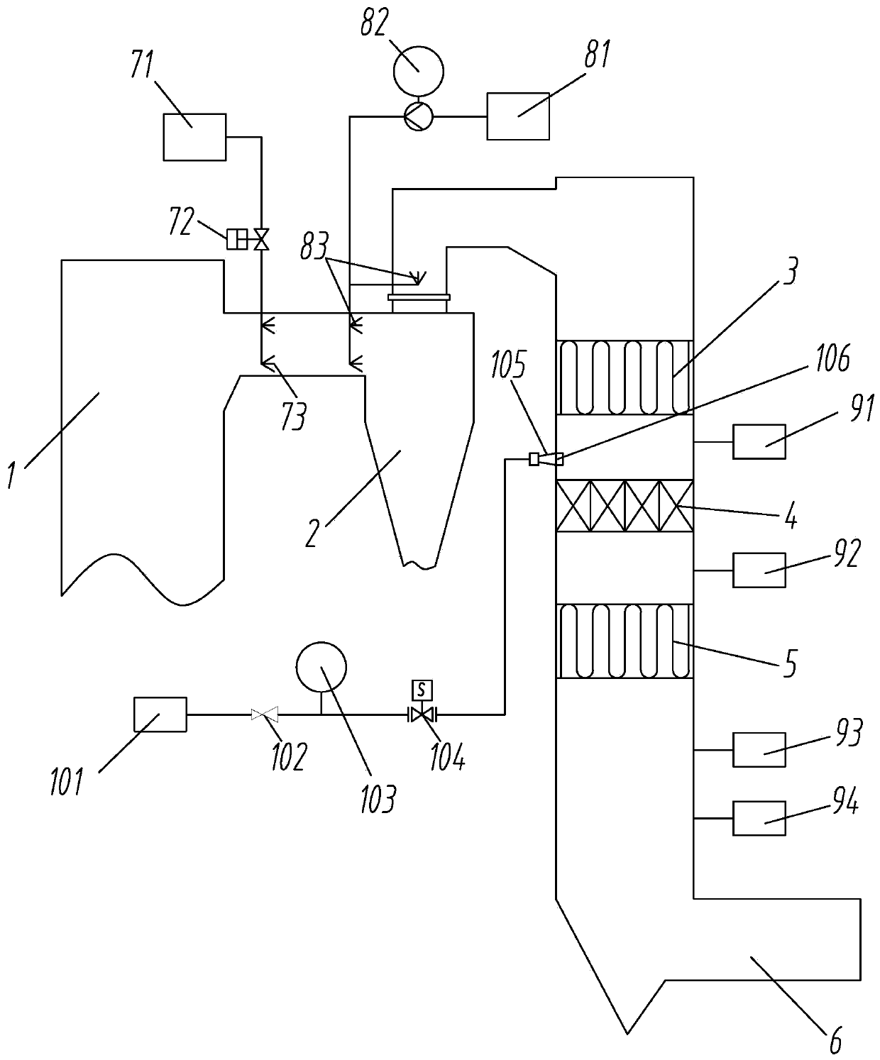
[0025] Such as figure 1 As shown, a system that uses ozone for flue gas denitration and efficiency enhancement includes a circulating fluidized bed boiler 1 and an online monitoring system. The gas outlet pipe of the circulating fluidized bed boiler 1 is connected with a cyclone separator 2, and the main part of the cyclone separator 2 The function is to remove the solid particles carried in the flue gas as much as possible. The gas outlet pipe of the cyclone separator 2 is connected with a flue 6, and the flue 6 is sequentially provided with a high temperature economizer 3, a denitration catalyst 4, and a medium/low temperature coal saving The outlet pipe of the circulating fluidized bed boiler 1 is connected with an ozone generating system. The ozone generating system can generate ozone and deliver the ozone to the outlet pipe of the circulating fluidized bed boiler 1, and the inlet pipe of the cyclone separator 2 and Ammonia water supply system is connected to the air outlet pipe. The ammonia water supply system can produce ammonia water and deliver the ammonia water to the inlet and outlet of the cyclone separator 2. The flue 6 is provided with a soot blowing system for cleaning the surface of the denitration catalyst 4 , The setting of the soot blowing system can ensure that the denitration catalyst 4 plays an effective role. The entire system is controlled by the DCS system. When the entire system is running, the high oxidizing property of ozone is used to couple the SNCR+SCR method to improve the denitration efficiency, thereby Meet high NO x It requires only one layer of denitration catalyst 4, which is arranged between the high temperature economizer 3 and the medium/low temperature economizer 5, which can save space and investment; among them, the medium/low temperature economizer 5 refers to You can use medium temperature economizer or low temperature economizer.
[0026] The ozone generation system includes an ozone generator 71, an ozone supply valve 72 and an ozone spray gun 73 connected in sequence. The various components are connected by pipelines to deliver ozone to a set position. The ozone spray gun 73 is arranged at the outlet of the circulating fluidized bed , Arrange 2-4 on both sides respectively, arranged vertically, the two spray guns on both sides are opposite, and each spray gun is inserted vertically into the outlet pipe of circulating fluidized bed boiler 1, which can ensure the sufficient supply of ozone. The ozone supply valve 72 is a pneumatic valve, which can easily control the delivery of ozone.
[0027] The ammonia water supply system includes an ammonia water storage tank 81, an ammonia water metering pump 82, and an ammonia water spray gun 83 which are connected in sequence. The various components are connected by pipelines. The ammonia water spray gun 83 is respectively arranged on the air inlet pipe and the air outlet pipe of the cyclone 2, thereby connecting The ammonia is delivered to the set position. Two to four ammonia spray guns 83 are arranged on both sides of the inlet of the cyclone 2 respectively, which are arranged along the vertical direction. The ammonia spray guns 83 on both sides are opposed to each other, and two ammonia spray guns 83 are arranged at the outlet. Each ammonia spray gun 83 is vertically inserted into the pipeline to ensure a sufficient supply of ammonia, and the ammonia metering pump 82 is a variable frequency pump, which can facilitate the control of the delivery of ammonia.
[0028] The online monitoring system includes a first pressure transmitter 91 disposed between the denitration catalyst 4 and the high temperature economizer 3, a second pressure transmitter 92 disposed between the denitration catalyst 4 and the medium/low temperature economizer 5, The ammonia leak detector 93 and the NOx/O2 analyzer 94, the first pressure transmitter 91 and the second pressure transmitter 92, which are arranged at the outlet end of the flue 6, can measure the pressure of the flue gas in the pipe and transmit the pressure signal To the DCS system, the settings of the ammonia leak detector 93 and the NOx/O2 analyzer 94 can monitor the NH in the flue gas 3 , NO x And O 2 The signal is transmitted to the DCS system, which is convenient for controlling the operation of the entire system through these signals.
[0029] The soot blowing system includes a compressed air tank 101, a pressure reducing valve 102, a third pressure transmitter 103, a solenoid valve 104 and a soot blower 105 which are connected in sequence. The various components are connected by pipelines. The compressed air tank 101 is compressed The air can be blown out from the outlet of the soot blower 105, so that the dust on the surface of the denitration catalyst 4 can be removed.
[0030] The outlet end of the soot blower 105 is connected with a protective device 106, such as figure 2 As shown, the protective device 106 includes a housing 212 with a ventilation cavity 201, one end of the housing 212 is provided with an air inlet 202 for connecting with the outlet end of the soot blower 105, and an air outlet plate 211 is slidingly connected in the ventilation cavity 201, The air outlet plate 211 is provided with an air outlet 207, one end of the air outlet plate 211 close to the air inlet 202 is provided with a return spring 203 connected to the side wall of the housing 212, and the other end of the air outlet plate 211 is provided with a plurality of support rods 208, The same dust-proof cover 206 is connected to the multiple support rods 208. Because the soot blower 105 is used in a very dusty environment, the nozzle hole at the outlet end of the soot blower 105 is often blocked, which affects the soot blower 105 Therefore, the outlet end of the soot blower 105 is connected with the air inlet 202 of the housing 212. When the compressed air is blown from the outlet end of the soot blower 105, the compressed air will blow onto the dust cover 206 and then overcome the return spring 203 The air outlet plate 211 is driven by the support rod 208 to slide in the ventilation chamber 201 after the spring force of the pressure, so that the compressed air can be smoothly discharged from the air outlet 207. When no compressed air is discharged, under the action of the return spring 203, the air outlet plate 211 The support rod 208 drives the dust cover 206 to move, thereby closing the opening of the ventilation cavity 201 to prevent dust from entering the ventilation cavity 201 and blocking the outlet hole 207 or the spray hole on the soot blower 105.
[0031] The end of the housing 212 away from the air inlet 202 is provided with an inner closed ring 204. The dust cover 206 is provided with an outer closed ring 205 corresponding to the inner closed ring 204. The diameter of the inner closed ring 204 is smaller than the diameter of the outer closed ring 205. When the dust cover 206 moves under the action of the return spring 203, the outer closed ring 205 just covers the inner closed ring 204, which can effectively prevent dust.
[0032] The outer surface of the inner closed ring 204 is provided with a first closed slope 210, so that the wall thickness of the inner closed ring 204 gradually decreases toward the outer closed ring 205, and the inner surface of the outer closed ring 205 is provided with a first closed slope The second closed slope 209 matched with 210 makes the wall thickness of the outer closed ring 205 gradually increase away from the outer closed ring 205. The arrangement of the first closed slope 210 and the second closed slope 209 can improve the outer closed ring 205 and the inner closed ring 205. The degree of adhesion between the closed rings 204 improves the sealing effect.

PUM

no PUM

Description & Claims & Application Information

We can also present the details of the Description, Claims and Application information to help users get a comprehensive understanding of the technical details of the patent, such as background art, summary of invention, brief description of drawings, description of embodiments, and other original content. On the other hand, users can also determine the specific scope of protection of the technology through the list of claims; as well as understand the changes in the life cycle of the technology with the presentation of the patent timeline. Login to view more.

Similar technology patents

Heating device for input smoke of SCR method denitration system

Owner:HUBEI QIANGDA ENVIRONMENTAL PROTECTION TECH CO LTD

Classification and recommendation of technical efficacy words

  • Improve denitrification efficiency
  • Save space

Ammonia flue gas desulfuration and denitration combined process and device

InactiveCN103041678APromote denitrificationImprove denitrification efficiencyUsing liquid separation agentPerfluorocarbons/hydrofluorocarbons captureFomesChemistry
Owner:ZHEJIANG TIANLAN ENVIRONMENTAL PROTECTION TECH
Why Eureka
Try Eureka