
Relay protection method and system for intelligently identifying switch fracture reignition

A technology of relay protection and intelligent identification, applied in the field of power equipment, can solve the problems of internal dust accumulation, heat accumulation, reduction of gas insulation capacity, etc., to prevent switch explosion accidents and ensure stable operation.

Pending Publication Date: 2020-06-12
GUANGDONG POWER GRID CO LTD +1
View PDF0 Cites 0 Cited by
  • Summary
  • Abstract
  • Description
  • Claims
  • Application Information

AI Technical Summary

Problems solved by technology

Since the inside of the switch has been broken down and seriously damaged, there will be problems such as internal dust accumulation and reduced gas insulation capacity. After the switch is reclosed, when the line fails again, it will cause a large amount of heat to accumulate at the moment of opening the switch and cause an explosion.

Method used


Image

  • Relay protection method and system for intelligently identifying switch fracture reignition
  • Relay protection method and system for intelligently identifying switch fracture reignition
  • Relay protection method and system for intelligently identifying switch fracture reignition

Examples


Embodiment 1

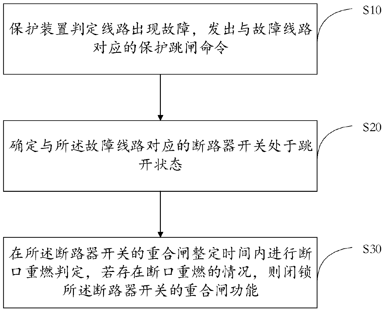
[0040] see Figure 1 ~ Figure 4 , this embodiment provides a relay protection method for intelligent identification of switch fracture re-ignition, which is suitable for the identification and treatment of switch fracture re-ignition during power grid operation, which can be executed by a relay protection system, through software and / or hardware accomplish.

[0041] Wherein, the relay protection system includes:

[0042] power lines;

[0043] a circuit breaker switch connected to the end of the power line;

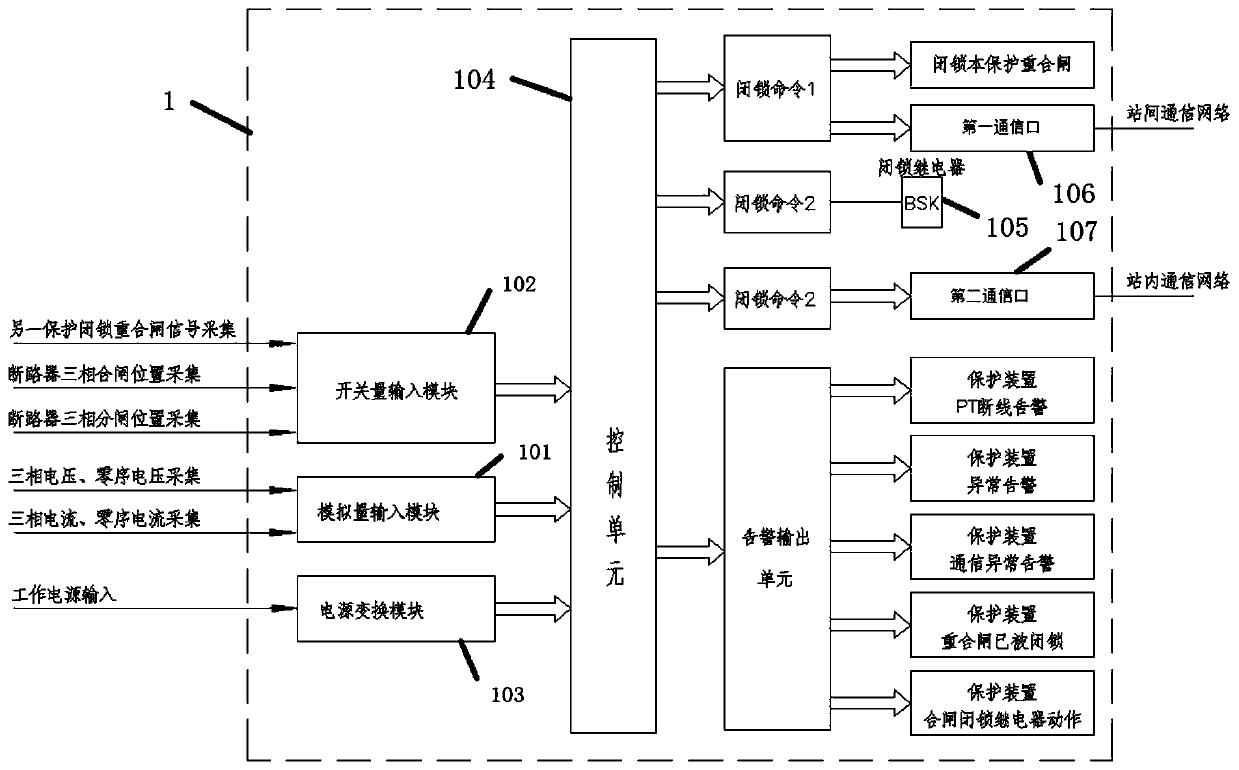
[0044] A protection device 1, the protection device 1 is electrically connected to the circuit breaker switch, and is used to control the opening and closing states of the circuit breaker switch.

[0045] The relay protection method includes:

[0046] S10: The protection device 1 determines that a fault occurs in the power line, and issues a protection trip command corresponding to the fault line.

[0047] S20: Determine that the circuit breaker switch corresponding t...

Embodiment 2

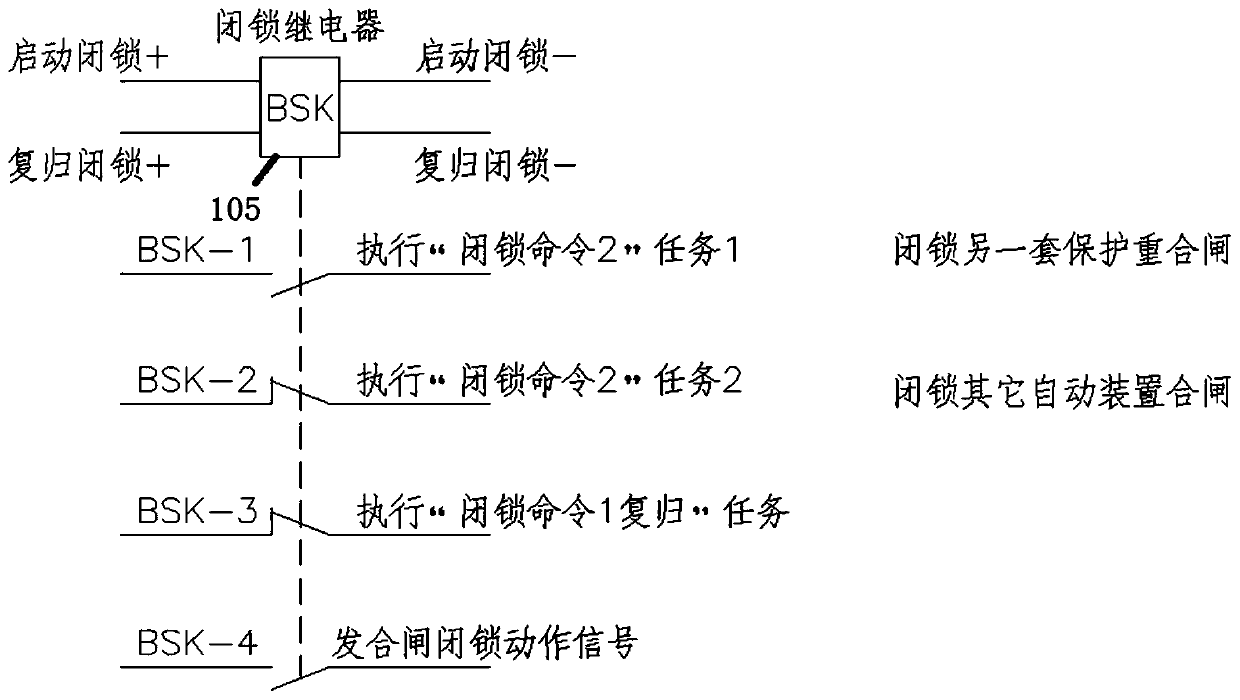
[0089] see Figure 2 ~ Figure 4 , the relay protection system provided in this embodiment can be used to implement the relay protection method provided in the embodiment of the present invention, and has corresponding functions and beneficial effects.

[0090] The relay protection system includes a power line, a circuit breaker switch connected in series with the power line, and a protection device 1 electrically connected to the circuit breaker switch and used to control the opening and closing state of the circuit breaker switch; the protection device 1 Including a control unit 104, the control unit 104 is used for:

[0091] Determine that the power line is faulty, and issue a protection trip command corresponding to the faulty line; determine that the circuit breaker switch corresponding to the faulty line is in a tripped state; perform a fracture reignition judgment within the reclosing setting time of the circuit breaker switch, If there is re-ignition of the fracture, t...


PUM


Abstract

The invention relates to the technical field of power equipment, and particularly discloses a relay protection method and system for intelligently identifying switch fracture reignition, and the method comprises the steps: S10, enabling a protection device to judge that a power line has a fault, and transmitting a protection tripping command corresponding to the fault line; S20, determining that acircuit breaker switch corresponding to the fault line is in a tripping state; and S30, carrying out fracture re-ignition judgment within the reclosing setting time of the circuit breaker switch, andif the fracture re-ignition condition exists, locking the reclosing function of the circuit breaker switch. The relay protection method for intelligently identifying reignition of the switch fracturecan take targeted protection measures for reignition of the switch fracture, prevent switch explosion accidents and ensure stable operation of a power system.

Description

technical field [0001] The invention relates to the technical field of electric power equipment, in particular to a relay protection method and system for intelligent identification of switch fracture re-ignition. Background technique [0002] Taking the opening as an example, when the circuit breaker switch is opened, an arc will be generated between the two contacts at the moment when the moving contact and the moving contact are separated, and a relatively high voltage is required to generate the arc, while maintaining the existence of the arc requires A relatively low voltage is enough, and the arc is often extinguished when the current crosses zero. At this time, if the dielectric insulation strength between the contacts is greater than the arc maintenance voltage between the contacts, the arc will be extinguished, otherwise the dielectric insulation between the contacts If the intensity is less than the arc maintenance voltage between the contacts, the medium will be b...

Claims


Application Information

Patent Timeline
Patent Type & Authority Applications(China)
IPC IPC(8): H02H7/26H02H3/06H02J13/00
CPCH02H3/066H02H7/262Y02E60/00Y04S10/20
Inventor 陈晓彬孙玉彤陈悦江王锃陈柏廷倪苗升李暖群刘耿彬孙旭张勇杰陈伟钦邢文忠王琪杨协伟郑其彦吴永峰王树浩
Owner GUANGDONG POWER GRID CO LTD
Learn More