Al technical title is built by PatSnap Al team. It summarizes the technical point description of the patent document.
A technology of wet mill and ball mill, applied in the field of wet mill, can solve the problems of no automation, high labor intensity and high labor cost, and achieve the effects of increasing slurry temperature control, increasing pressure monitoring in the drum, and reducing labor costs.
Pending Publication Date: 2020-06-16
株洲长江硬质合金设备股份有限公司
View PDF7 Cites 1 Cited by
Summary
Abstract
Description
Claims
Application Information
AI Technical Summary
This helps you quickly interpret patents by identifying the three key elements:
Problems solved by technology
Method used
Benefits of technology
Problems solved by technology
Due to various reasons, the two ball mills are basically not automated for the time being. When they are used, there are many manual components and high labor intensity.
Taking the tilting wet mill as an example, when feeding materials, the gland needs to be opened manually, the materials are fed manually, and the solvent is added. It becomes a gaseous state to generate pressure, and it is necessary to manually "deflate" regularly to eliminate the risk of cylinder explosion. After ball milling, the gland is manually replaced with a discharge hopper. It is necessary to tilt the cylinder several times, add solvent and discharge the slurry to achieve For the purpose of cleaning, this operation method is time-consuming and laborious, and there are many steps in the operation, which seriously reduces the production efficiency of the enterprise, and the labor cost is relatively high.
Method used
Image
Click on the blue label to locate the original text in one second.
Reading with bidirectional positioning of images and text.
Examples
Embodiment
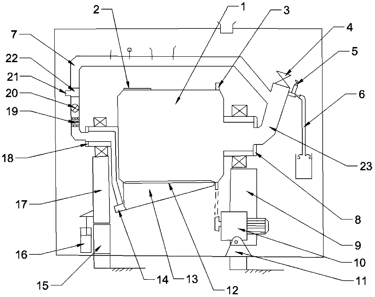
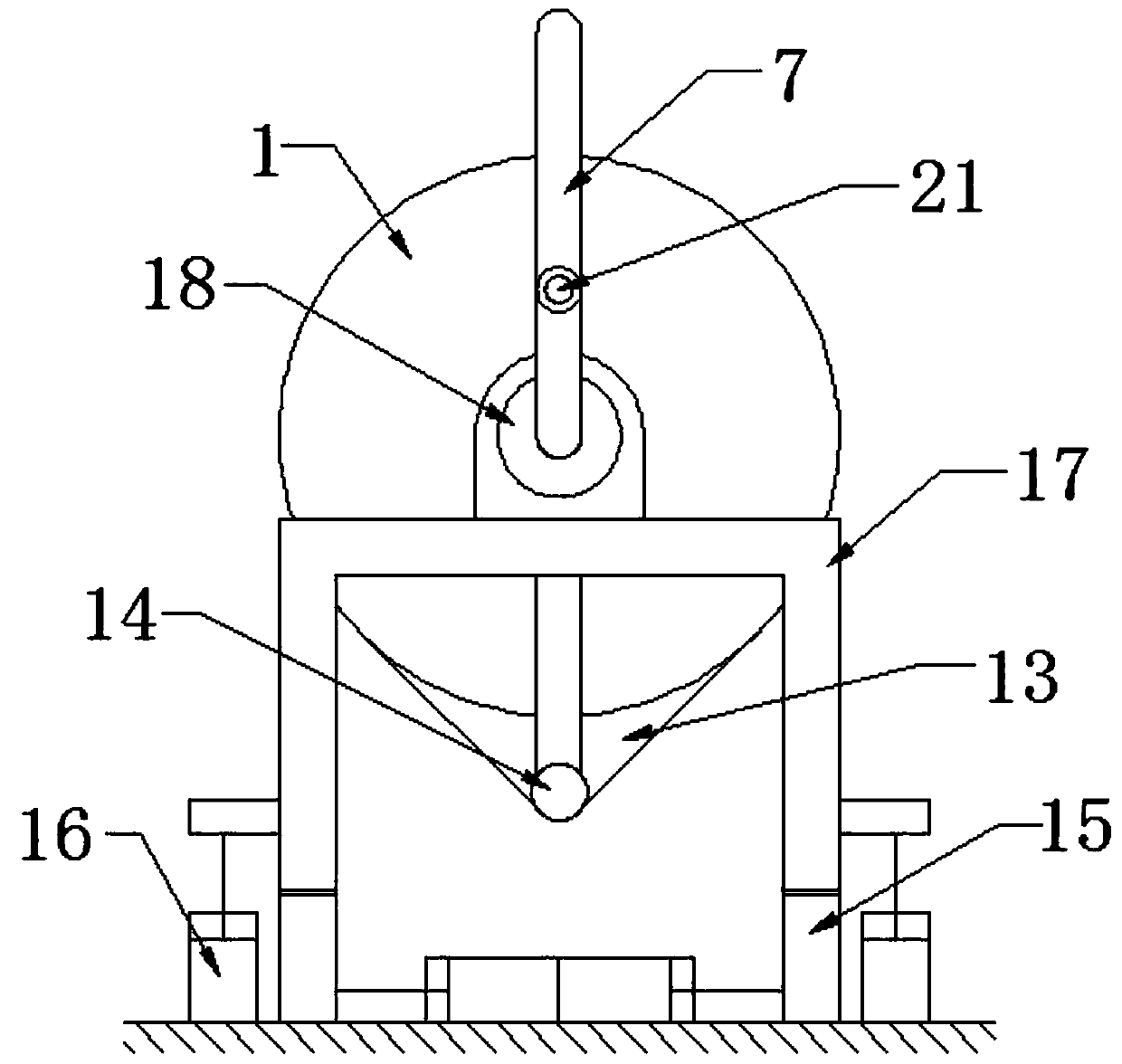
[0023] Such as Figure 1-2 As shown, a wet mill includes a ball mill cylinder 1, the upper part of the ball mill cylinder 1 is provided with a ball outlet 2, the surface of the ball mill cylinder 1 is fixedly sleeved with a sprocket 3 and is connected to the motor 10 through a transmission chain, and the lower part of the ball mill cylinder 1 There is an inclined bucket 13, and the bottom of the inclined bucket 13 is provided with a slagging outlet 14, and the inner lower end of the ball mill cylinder 1 is also equipped with a ball grid 12, which is located between the ball mill cylinder 1 and the inclined bucket 13 and is connected to the ball mill. Cylinder 1 and inclined bucket 13, the cylinder mouth of ball mill cylinder 1 is connected with feed pipe 23, the end of feed pipe 23 away from ball mill cylinder 1 is feed inlet 4 and is provided with feed valve, and feed pipe 23 is far away from ball mill cylinder 1 The two sides are respectively connected with the circulation p...
PUM
Abstract
The invention discloses a wet mill. The wet mill comprises a ball milling cylinder, the upper portion of the ball milling cylinder is provided with a ball outlet and a chain wheel respectively, the lower portion of the ball milling cylinder is provided with an inclined hopper and a slag discharging port, the lower end of the inner portion of the ball milling cylinder is further provided with a ball barrier, one side of the ball milling cylinder is connected with a feeding pipe, the end, away from the ball milling cylinder, of the feeding pipe is a feeding port, the two sides of the feeding pipe are connected with a circulating pipe and a solvent inlet pipe respectively, one side of the solvent inlet pipe is connected with an exhaust pipe, the other end, away from the feeding pipe, of the circulating pipe is connected with the slag discharging port formed in the lower portion of the ball milling cylinder, a filtering device, a slurry pump and a three-way valve are arranged in a pipe body, close to the slag discharging port, of the circulating pipe respectively. The wet mill has the beneficial effects that automatic feeding, wet milling and exhausting are achieved, slurry temperaturecontrol and in-cylinder pressure monitoring are added, the whole equipment operation process is controlled by a computer, full-automatic operation of the wet mill is achieved, the labor cost of an enterprise is reduced, the production efficiency of the enterprise is improved, and meanwhile the potential safety hazard that a cylinder is prone to explosion is avoided.
Description
technical field [0001] The invention relates to the technical field of cemented carbide wet grinding, in particular to a wet grinding machine. Background technique [0002] Wet grinding is to put balls, powder, and solvent into the grinding cylinder according to a certain ratio for ball grinding. The wet grinding produced by cemented carbide has some characteristics: the powder is very hard, the solvent has a low boiling point, and requires low temperature and air isolation to prevent oxygenation. , high uniformity requirements, currently there are two main methods used: one is the tilting wet mill of rolling ball mill, and the other is vertical stirring ball mill; [0003] At present, the domestic cemented carbide industry mostly uses tilting wet grinding machines (more than 90%). Due to various reasons, the two kinds of ball mills are basically not automated for the time being. When they are used, there are many manual components and high labor intensity. Taking the tilt...
Claims
Application Information
Patent Timeline
Application Date:The date an application was filed.
Publication Date:The date a patent or application was officially published.
First Publication Date:The earliest publication date of a patent with the same application number.
Issue Date:Publication date of the patent grant document.
PCT Entry Date:The Entry date of PCT National Phase.
Estimated Expiry Date:The statutory expiry date of a patent right according to the Patent Law, and it is the longest term of protection that the patent right can achieve without the termination of the patent right due to other reasons(Term extension factor has been taken into account ).
Invalid Date:Actual expiry date is based on effective date or publication date of legal transaction data of invalid patent.