Clamping device and machine tool
A clamping device and machine tool technology, applied in positioning devices, auxiliary devices, clamping, etc., can solve the problems of inconvenient clamping, unsatisfactory processing efficiency and effect, etc., to achieve convenient maintenance, better processing efficiency and effect, Wide range of effects
- Summary
- Abstract
- Description
- Claims
- Application Information
AI Technical Summary
Problems solved by technology
Method used
Image

Examples
Embodiment 1
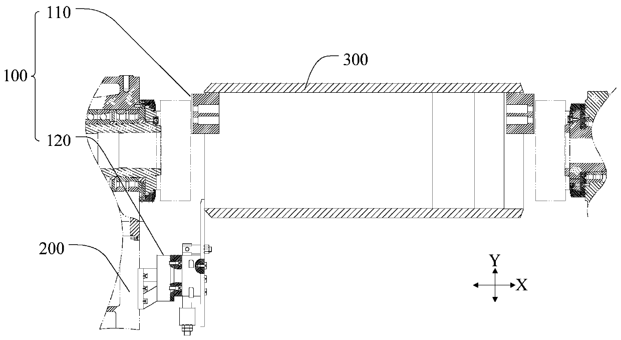
[0040] Such as figure 1 As shown, this embodiment provides a clamping device 100 which is arranged on a machine tool 200 and includes: a clamping assembly 110 and a positioning assembly 120 . The clamping assembly 110 is suitable for clamping the component 300 to be processed. The positioning assembly 120 includes a driving part 122 and a positioning part 124 . Wherein, the driving part 122 drives the positioning part 124 to move forward along the first direction Y, so that the positioning part 124 stops the part 300 to be processed, and the driving part 122 drives the positioning part 124 to move backward along the first direction Y, so that the positioning part 124 avoids the part 300 to be processed.
[0041] The machine tool 200 of this embodiment may specifically be a numerically controlled machine tool, which is used for cutting the component 300 to be processed. The part to be processed 300 has a cylindrical or cylindrical structure. For example, the part 300 to be ...
Embodiment 2
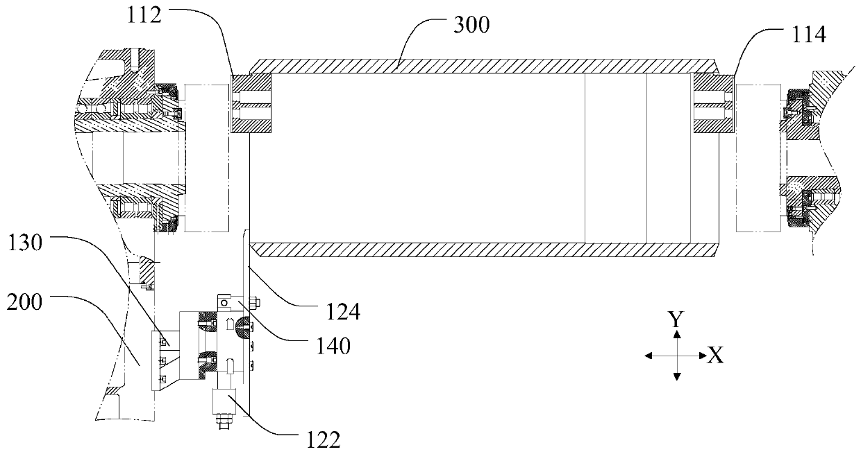
[0052] Such as figure 2 As shown, this embodiment provides a clamping device 100, and in addition to the technical features of the above-mentioned embodiment 1, this embodiment further includes the following technical features.
[0053] The clamping assembly 110 includes: a first clamping portion 112 and a second clamping portion 114 . The second clamping portion 114 is disposed opposite to the first clamping portion 112 along the second direction X, and together with the first clamping portion 112 defines a space suitable for accommodating the component 300 to be processed. Wherein, the second direction X and the first direction Y are perpendicular to each other.
[0054] In this embodiment, the first direction Y is a vertical direction, and the second direction X is a horizontal direction. During processing, the component 300 to be processed is placed horizontally. The component to be processed 300 has a cylindrical or cylindrical structure, which includes an upper botto...
Embodiment 3
[0059] Such as figure 2 As shown, this embodiment provides a clamping device 100, and in addition to the technical features of any of the above-mentioned embodiments, this embodiment further includes the following technical features.
[0060] The clamping device 100 further includes: a supporting part 130 . The support unit 130 is provided between the driving unit 122 and the machine tool 200 . Wherein, the driving part 122 is connected to the machine tool 200 through the supporting part 130 .
[0061] The supporting part 130 of this embodiment can specifically be a supporting frame, a supporting plate or a supporting rib, which connects and fixes the driving part 122 on the machine tool 200, which is convenient for the installation and fixing of the driving part 122 and can prevent the driving part 122 from being damaged due to work. resulting in shaking or vibration. Therefore, the setting of the supporting part 130 can ensure the stability of the positioning part 124 wh...
PUM
| Property | Measurement | Unit |
|---|---|---|
| diameter | aaaaa | aaaaa |
Abstract
Description
Claims
Application Information