Charging pile for new energy automobile

A technology of new energy vehicles and charging piles, applied in electric vehicle charging technology, charging stations, electric vehicles, etc., can solve problems such as short circuit of charging lines, easy water ingress, leakage of electricity, etc., and achieve the effect of weakening inertia and reducing damage

Active Publication Date: 2020-06-16
UNIV FOR SCI & TECH ZHENGZHOU
View PDF5 Cites 15 Cited by
  • Summary
  • Abstract
  • Description
  • Claims
  • Application Information

AI Technical Summary

Problems solved by technology

[0003] However, the existing new energy vehicle charging piles usually use an external exposed installation structure, and are usually fixedly installed at the end of the parking space. When the new energy vehicle needs to be charged, the car is usually reversed (or driven into ) in the parking space, so that the charging hole on the car is close to the position of the charging pile, but the existing charging pile lacks buffer protection measures for external collision impact. When the driver parks the car in the parking space, if an operation error occurs As a brake) or hit the charging pile due to poor vision when reversing, the charging pile is prone to damage when it is hit by an external force, reducing the safety of the charging pile;
[0004] Another one is that most of the existing charging piles for new energy vehicles are not equipped with rainproof measures. Exposure to rain and rain-proof rubber and other aging will easily lead to water leakage and other problems, and serious problems will cause a short circuit in the charging line, resulting in serious situations such as fire and combustion;

Method used


Image

  • Charging pile for new energy automobile
  • Charging pile for new energy automobile
  • Charging pile for new energy automobile

Examples


Embodiment 1

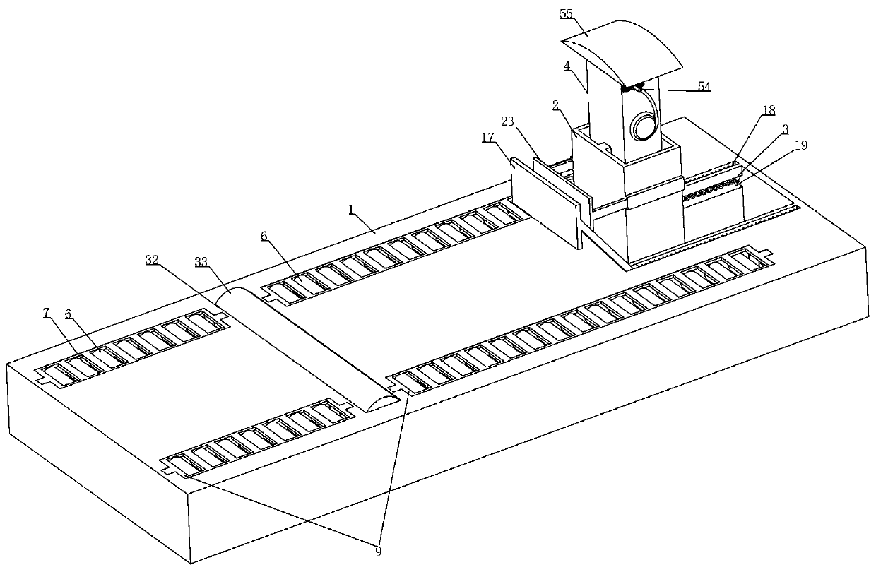
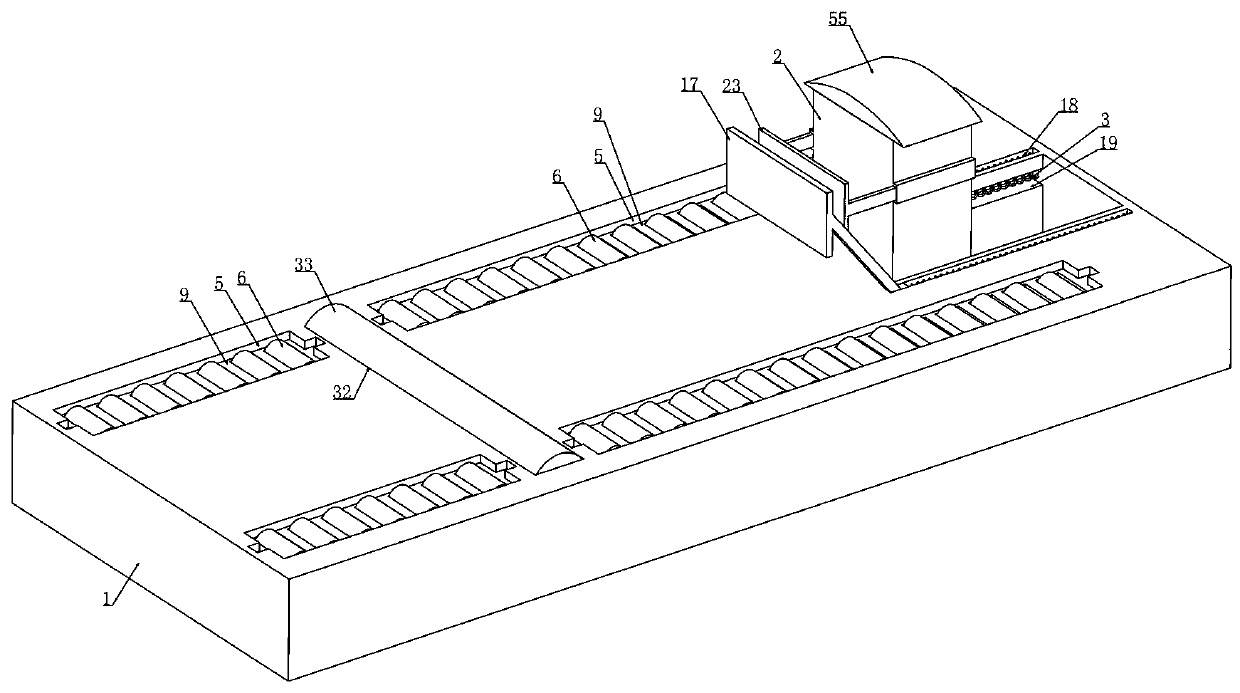
[0041] Embodiment 1, this embodiment provides a charging pile for new energy vehicles, refer to the attached figure 1 As shown, including the base 1, it is characterized in that a protective box 2 is installed laterally on the base 1 and the protective box 2 is locked by a locking device arranged in the base 1 (in normal charging or the charging box 4 shrinks to the protective box 2 When inside, the protective box 2 is locked), and the charging box 4 is vertically slid inside the protective box 2 (the charging box 4 is connected with an external charging line, and the upper side of the charging box 4 is provided with a charging gun 54) And the charging box 4 is driven by the lifting device arranged in the protective box 2, referring to the attached figure 1 As shown, a trigger device is installed vertically slidingly on the base 1 at a distance from the protective box 2. When the trigger device is triggered, the lifting device is controlled to drive the charging pile up or dow...

Embodiment 2

[0050] Embodiment 2, on the basis of embodiment 1, with reference to appended figure 1 , 2 As shown, the first-level buffer device is a first-level buffer plate 17 mounted on the base 1 by lateral sliding, and the two longitudinal ends of the first-level buffer plate 17 are respectively installed on the base 1 by laterally sliding on the slanting rod. There is a third spring 18 connected between the base 1. When the automobile hits the primary buffer plate 17, it will drive the primary buffer plate 17 to move and compress the third spring 18 to realize the buffering of the inertial potential energy of the automobile. Refer to the attached Figure 5 As shown, we are provided with a chute 19 in the base 1 that is horizontally slidable with the protective box 2, so that the protective box 2 can slide along the chute 19 after being hit by the car, and we set the first spring 3 on the sliding chute. In the groove 19, when the protective box 2 slides along the chute 19, the first s...

Embodiment 3

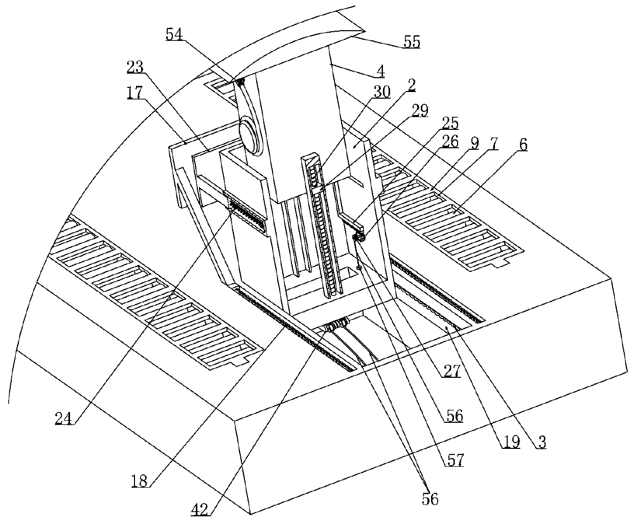
[0052] Embodiment 3, on the basis of embodiment 2, with reference to appended image 3 As shown, the secondary buffer device includes a secondary buffer plate 23 that is horizontally slidably mounted on the longitudinal side walls of the protective box 2, and a fourth spring 24 is connected between the secondary buffer plate 23 and the protective box 2. When the primary buffer plate When 17 collides with the secondary buffer plate 23, it drives the secondary buffer plate 23 to move along the side wall of the protective box 2 and compresses the fourth spring 24, and the two locking columns 21 are fixedly connected through the connecting rod 28, as attached Figure 6As shown, and we are integrally provided with connecting column 57 on the connecting rod 28, the upper end of the connecting column 57 is connected with the wire rope 56 wound on the unlocking pulley 27, and we are provided with connecting column 57 on the bottom wall of the protective box 2. A matching circular slid...


PUM


Abstract

The invention relates to a charging pile for a new energy automobile. The charging pile effectively solves the problems that an existing automobile charging pile is poor in safety protection measure and prone to being damaged. According to the technical scheme, the method comprises the following steps of: ; the new energy automobile charging pile can be contracted when not in use; external rainwater is prevented from eroding the device; when an automobile collides with the charging pile due to misoperation, the charging pile is started; firstly, the impact force acts on the first buffer plateand absorbs most impact force at the moment of automobile impact; and then the automobile acts on the second buffer plate, positioning of the protection box is relieved through the second buffer plate, when the automobile forces the protection box to slide, the wheels make contact with the multiple sets of rotating rollers and idle, the forward inertia of the automobile is weakened, and thereforedamage to the charging pile is reduced.

Description

technical field [0001] The invention relates to the technical field of new energy vehicles, in particular to a charging pile for new energy vehicles. Background technique [0002] The function of the electric pile is similar to the fuel dispenser in the gas station. It can be fixed on the ground or wall, and installed in the parking lot or charging station of public buildings and residential areas. The input end of the charging pile is directly connected to the AC power grid, and the output end is equipped with charging The plug is used to charge new energy vehicles; [0003] However, the existing new energy vehicle charging piles usually use an external exposed installation structure, and are usually fixedly installed at the end of the parking space. When the new energy vehicle needs to be charged, the car is usually reversed (or driven into ) in the parking space, so that the charging hole on the car is close to the position of the charging pile, but the existing charging...

Claims


Application Information

Patent Timeline
Patent Type & Authority Applications(China)
IPC IPC(8): B60L53/31
CPCB60L53/31Y02T10/70Y02T10/7072Y02T90/12
Inventor 张玉华杨丽彦郭鹤贾华坡陈林林
Owner UNIV FOR SCI & TECH ZHENGZHOU
Why Eureka
Try Eureka