Feeding device and optical module testing system
An optical module testing and material tray technology, which is used in optical instrument testing, transmission monitoring/testing/fault measurement systems, measuring devices, etc., can solve problems such as low feeding efficiency, reduce labor intensity and improve feeding efficiency. and the effect of mechanization
- Summary
- Abstract
- Description
- Claims
- Application Information
AI Technical Summary
Problems solved by technology
Method used
Image

Examples
Embodiment 1
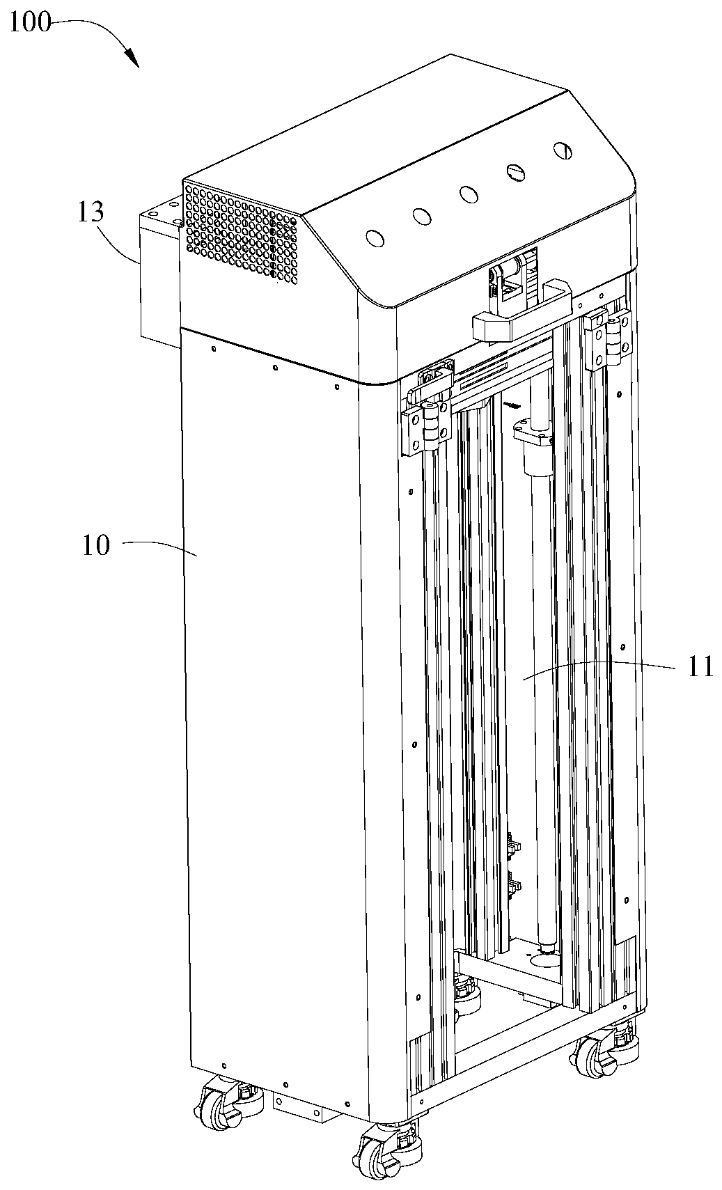
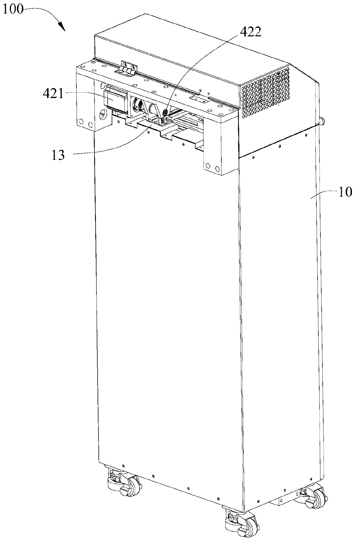
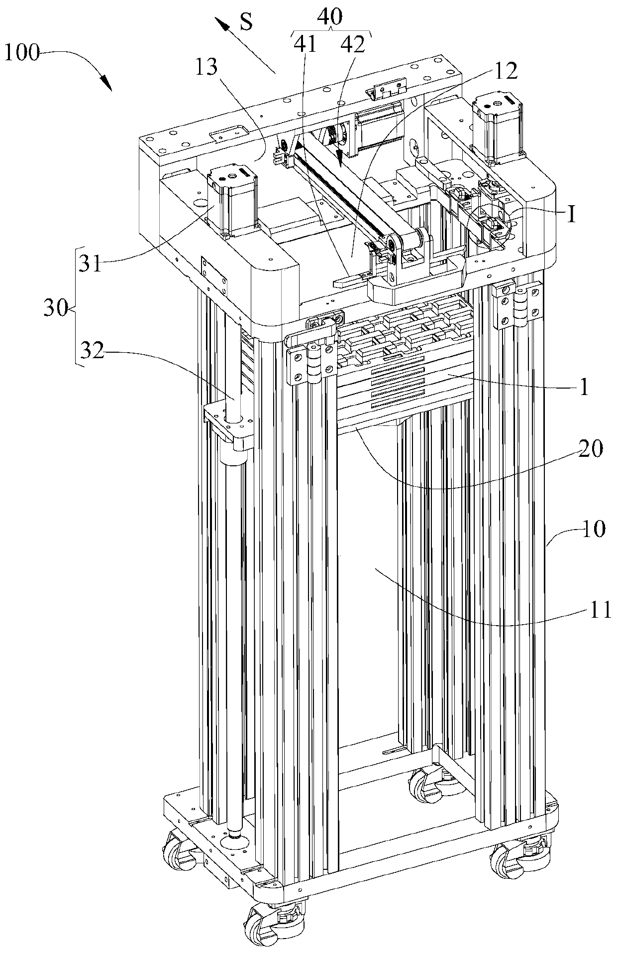
[0038] see Figure 1-Figure 6 , shows the feeding device 100 in the first embodiment of the present invention, including a frame 10, a carrier plate 20 that lifts and moves on the frame 10, a lifting drive assembly 30 that provides power for lifting and moving the carrier plate 20, The pushing mechanism 40 that performs the discharging action, and the partition assembly 50 that separates the stacked trays, wherein:
[0039] The inside of the frame 10 is provided with a cavity 11, and the carrier plate 20 moves up and down in the cavity 11. The top of the frame 10 is provided with an opening 12 communicating with the cavity 11. A single tray or multiple trays can be placed on the carrier plate 20. A stack of trays formed by stacking and placing the trays, in order to improve the feeding efficiency, each discharge is selected to place the stack of trays on the carrier plate 20, which can reduce the number of times the carrier plate 20 drops and refills and improves the feeding e...
Embodiment 2
[0051] see Figure 10-Figure 12 , shows the feeding device 100 in the second embodiment of the present invention, the difference between the feeding device 100 in this embodiment and the feeding device 100 in the first embodiment is that in order to improve the degree of mechanical automation, this The feeding device 100 in the embodiment also includes a first sensor 60, a second sensor 70 and a third sensor 80, wherein:
[0052] The first sensor 60 is arranged at the opening 12 and communicated with the second motor 31. When the first sensor 60 detects that the top tray reaches the height of the push plate 41, the lifting drive assembly 30 drives the carrier plate 20 to drop a predetermined stroke ( Such as 10cn), to automatically separate the top-level material tray from the lower-level material tray after the top-level material tray is in place.
[0053] The second sensor 70 is arranged at the tray outlet 13, and communicates with the first motor 421. When the second senso...
Embodiment 3
[0058] The embodiment of the present invention also proposes an optical module testing system, please refer to Figure 13-Figure 14 , shows the optical module testing system in the third embodiment of the present invention, including the optical module testing equipment 200 and the feeding device 100, the optical module testing equipment 200 includes the material assembly line 201, and the feeding device 100 can be any of the above-mentioned embodiments Among them, the feeding device 100 is connected to the optical module testing equipment 200, and the tray outlet 13 of the feeding device 100 is connected to the material assembly line 201, so that the feeding device 100 can continuously automatically deliver the device to the material assembly line 201. There is a tray 1 of the optical module to be tested, so that the tray 1 with the optical module to be tested is continuously delivered to the optical module testing device 200 . During testing, the optical module testing equip...
PUM
 Abstract
Description
Claims
Application Information
 - R&D
- Intellectual Property
- Life Sciences
- Materials
- Tech Scout
- Unparalleled Data Quality
- Higher Quality Content
- 60% Fewer Hallucinations
Browse by: Latest US Patents, China's latest patents, Technical Efficacy Thesaurus, Application Domain, Technology Topic, Popular Technical Reports.
© 2025 PatSnap. All rights reserved.Legal|Privacy policy|Modern Slavery Act Transparency Statement|Sitemap|About US| Contact US: help@patsnap.com