Household water purification equipment based on deep purification
A kind of water purification equipment, deep technology, applied in water/sewage treatment equipment, water/sewage treatment, chemical instruments and methods, etc., can solve water pollution, affect the effective use of water, human health and environmental adverse effects, etc., to achieve The effect of improving efficiency and effectiveness
- Summary
- Abstract
- Description
- Claims
- Application Information
AI Technical Summary
Problems solved by technology
Method used
Image

Examples
Embodiment 1
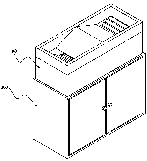
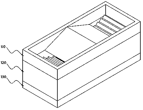
[0073] see Figure 1-Figure 17 As shown, the present invention provides household water purification equipment based on deep purification, including an initial filter chamber 100 and a deep purification box 200 installed at the bottom of the initial filtration warehouse 100, and the interior of the deep purification box 200 includes at least:
[0074] Filler purification device 210, the filler purification device 210 comprises a filler purification box 211, the filler purification box 211 is a cylindrical structure with an opening on the top, the inside of the filler purification box 211 is provided with a filler purification cylinder 212, and the interior of the filler purification cylinder 212 is provided with There is a filter cylinder 2125 for placing water purification fillers. The water purification fillers are preferably alum. After alum dissolves in water, it is ionized to produce Al3+, which combines with OHˉ produced by water ionization to form aluminum hydroxide, and...
PUM
 Abstract
Description
Claims
Application Information