Safety system for preventing gas leakage and explosion
A gas leakage prevention and safety system technology, applied in the field of gas transmission control equipment, can solve the problems of complex manufacturing process, high production cost, low production efficiency, etc., and achieve the effect of convenient control, convenient operation and simple structure
- Summary
- Abstract
- Description
- Claims
- Application Information
AI Technical Summary
Problems solved by technology
Method used
Image

Examples
Embodiment 1
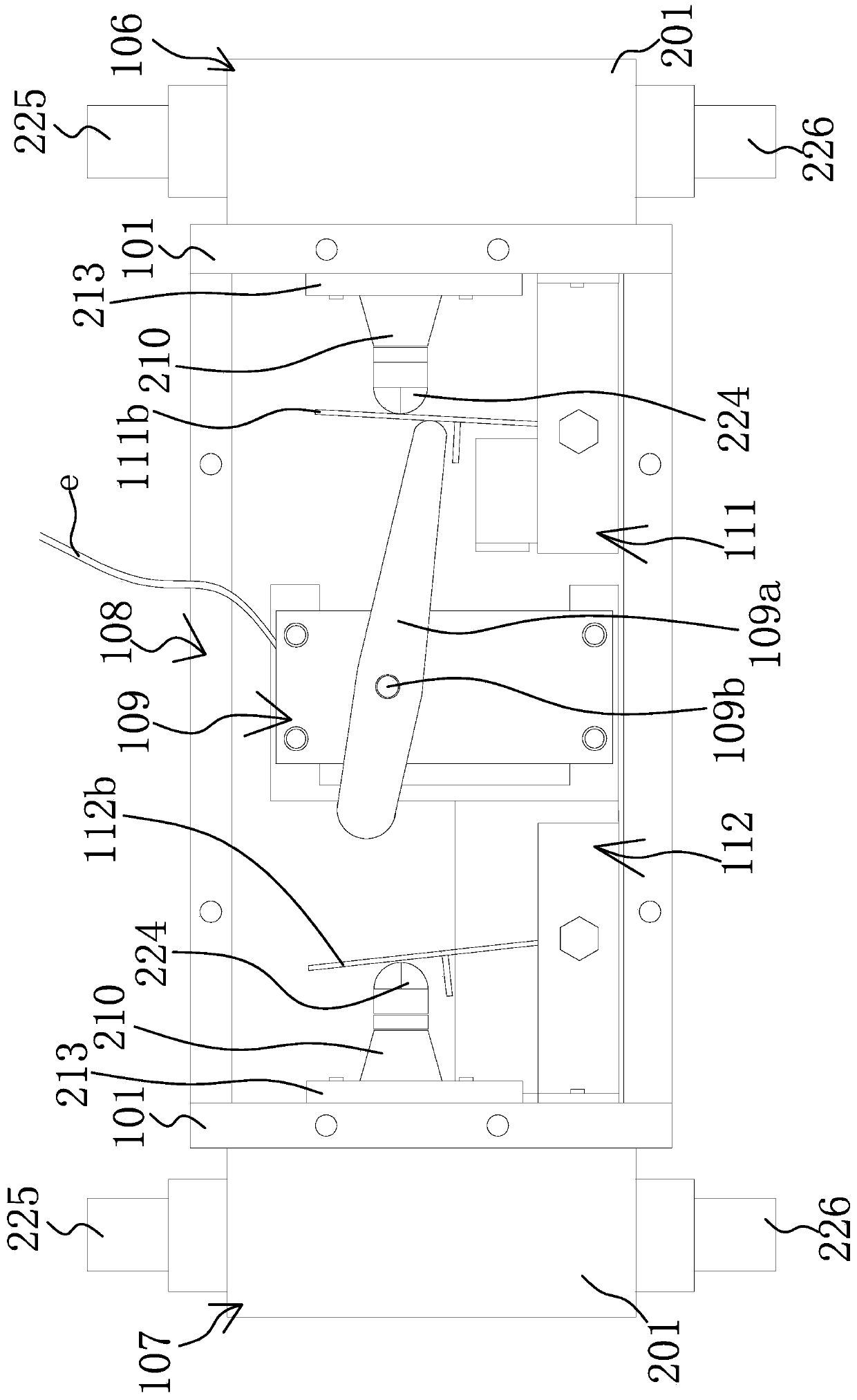
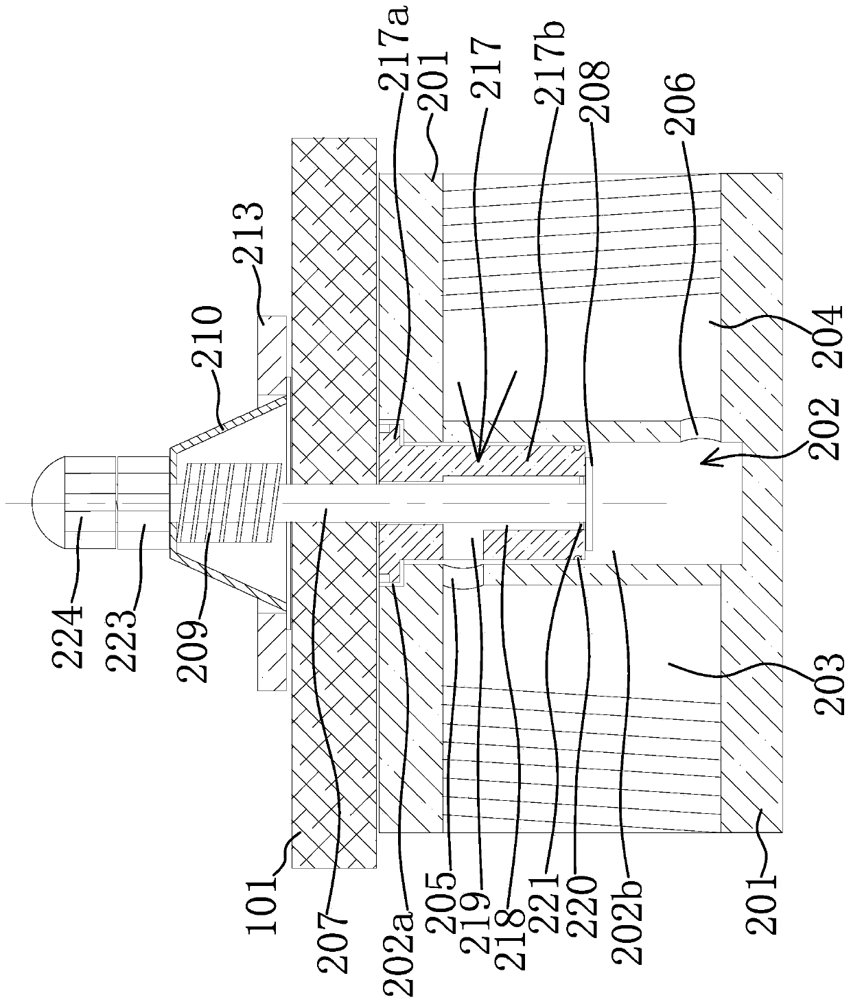
[0050] Such as Figures 3 to 4 As shown, the push-type valve includes a valve seat 201, a valve cavity 202 is provided in the middle of one side of the valve seat 201, and one end of the push-type structure is inserted. The first air port 203 and the second air port 204 are respectively opened, and the first air port 203 and the second air port 204 communicate with the valve cavity 202 through the first connection hole 205 and the second connection hole 206 located inside the valve seat 201 respectively, and the push type structure When not pressed, the first connecting hole 205 and the second connecting hole 206 are not connected, and when pressed, the first connecting hole 205 and the second connecting hole 206 are sealed and connected.
[0051] Preferably, the first air port 203 and the second air port 204 are respectively connected to the first external short pipe 225 and the second external short pipe 226 through connecting threads in the first air port, which facilitates...
Embodiment 2
[0058] This embodiment is basically the same as Embodiment 1, except that the elastic reset assembly also includes an elastic sealing cover 210 arranged between the valve seat 201 and the pressing valve stem 207 to prevent gas leakage in the valve chamber 202, and reset The spring 209 is arranged in the elastic sealing cover 210 , and presses the valve rod 207 to seal the cover sealing hole 211 passing through the elastic sealing cover 210 .
[0059] It should be noted that, due to the setting of the elastic sealing cover 210 at this time, one end of the return spring 209 does not need to be fixed on the pressing valve stem 207, and it can be sleeved on the pressing valve stem 207 to realize the pressure on the pressing valve stem 207. It can move freely, which greatly facilitates the disassembly and assembly of the return spring 209, because its moving position is limited by the elastic sealing cover 210 in this embodiment.
[0060] In addition, the elastic return assembly ca...
Embodiment 3
[0065] Such as Figures 3 to 6 As shown, this embodiment is basically the same as Embodiments 1 and 2, except that the push-type structure here also includes at least a part of the valve stem seat 217 located in the valve cavity 202 on the valve seat 201, and the valve stem seat 217 There is a valve stem channel 218 for a section of the pressing valve stem 207 to move back and forth inside, and the position where the first sealing member 208 is provided on the pressing valve stem 207 protrudes out of the valve when the pressing valve stem 207 is pressed and when it is not pressed. The stem seat 217 is inserted into the valve chamber 202, and the first sealing member 208 abuts against the opposite inner end of the stem seat 217 when it is not pressed to block the communication between the stem passage 218 and the second connecting hole 206. The stem passage 218 One side is opened with a first connecting channel 219 communicating with the first connecting hole 205, and the first...
PUM
 Abstract
Description
Claims
Application Information
 - R&D
- Intellectual Property
- Life Sciences
- Materials
- Tech Scout
- Unparalleled Data Quality
- Higher Quality Content
- 60% Fewer Hallucinations
Browse by: Latest US Patents, China's latest patents, Technical Efficacy Thesaurus, Application Domain, Technology Topic, Popular Technical Reports.
© 2025 PatSnap. All rights reserved.Legal|Privacy policy|Modern Slavery Act Transparency Statement|Sitemap|About US| Contact US: help@patsnap.com