Optical fiber sensing system and method for multi-channel remote measurement

An optical fiber sensing system and a technology for detecting optical fibers, which are applied in the field of optical fiber sensing systems for multi-channel telemetry to achieve the effect of increasing the repetition frequency

Pending Publication Date: 2020-06-16
UNIV OF ELECTRONICS SCI & TECH OF CHINA
View PDF0 Cites 0 Cited by
  • Summary
  • Abstract
  • Description
  • Claims
  • Application Information

AI Technical Summary

Problems solved by technology

[0004] The technical problem to be solved by the present invention is: the traditional distributed vibration sensing system cannot use high repetition frequency pulsed light under the premise of long-distance detection. The present invention provides a multi-channel telemetry optical fiber transmission sensing system and method

Method used


Image

  • Optical fiber sensing system and method for multi-channel remote measurement
  • Optical fiber sensing system and method for multi-channel remote measurement

Examples


Embodiment 1

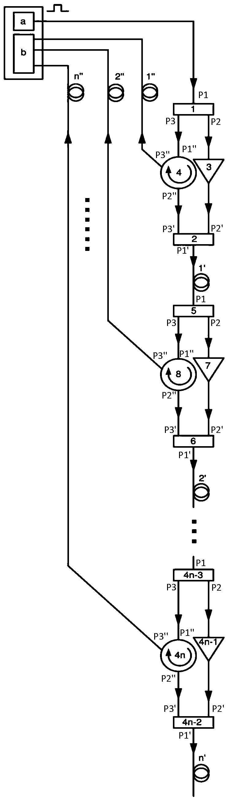
[0037] This embodiment provides a multi-channel telemetry optical fiber sensing system, including a pulsed light source system, a phase demodulation module and N circulators, the pulsed light source system and the phase demodulation module are connected by optical cable communication, and N is ≥ 2 Positive integer; N circulators are arranged sequentially along the transmission direction of the optical cable, and the arrangement structure of N circulators includes series connection or parallel connection. For each circulator, 1 end of the circulator is used to input the pulsed optical signal, and the 2 ends of each circulator are connected to the sensing fiber, and the Rayleigh scattered light signal is generated during the transmission of the pulsed optical signal through the sensing optical fiber, along the pulse The opposite direction of the optical signal transmission direction enters through port 2 of the circulator, outputs from port 3, and finally enters the phase demodul...

Embodiment 2

[0040] This embodiment provides a multi-channel telemetry optical fiber sensing system, which is further improved on the basis of Embodiment 1. When N circulators are arranged in a series structure: N wave splitters, N optical Isolator and N multiplexers; one structural unit is 1 demultiplexer, 1 circulator, 1 optical isolator and 1 multiplexer, and there are N structural units in total; along the transmission direction, each In a structural unit, the wave splitter is located at the upstream end, the wave combiner is located at the downstream end, and the circulator combined with the optical isolator is connected in parallel between the wave splitter and the wave combiner; N structural units are connected in series through the sensing fiber along the transmission direction , the wave splitter of the first structural unit is connected with the pulse light source system, and the wave splitter of the Nth structural unit is connected with the wave combiner of the N-1th structural u...

Embodiment 3

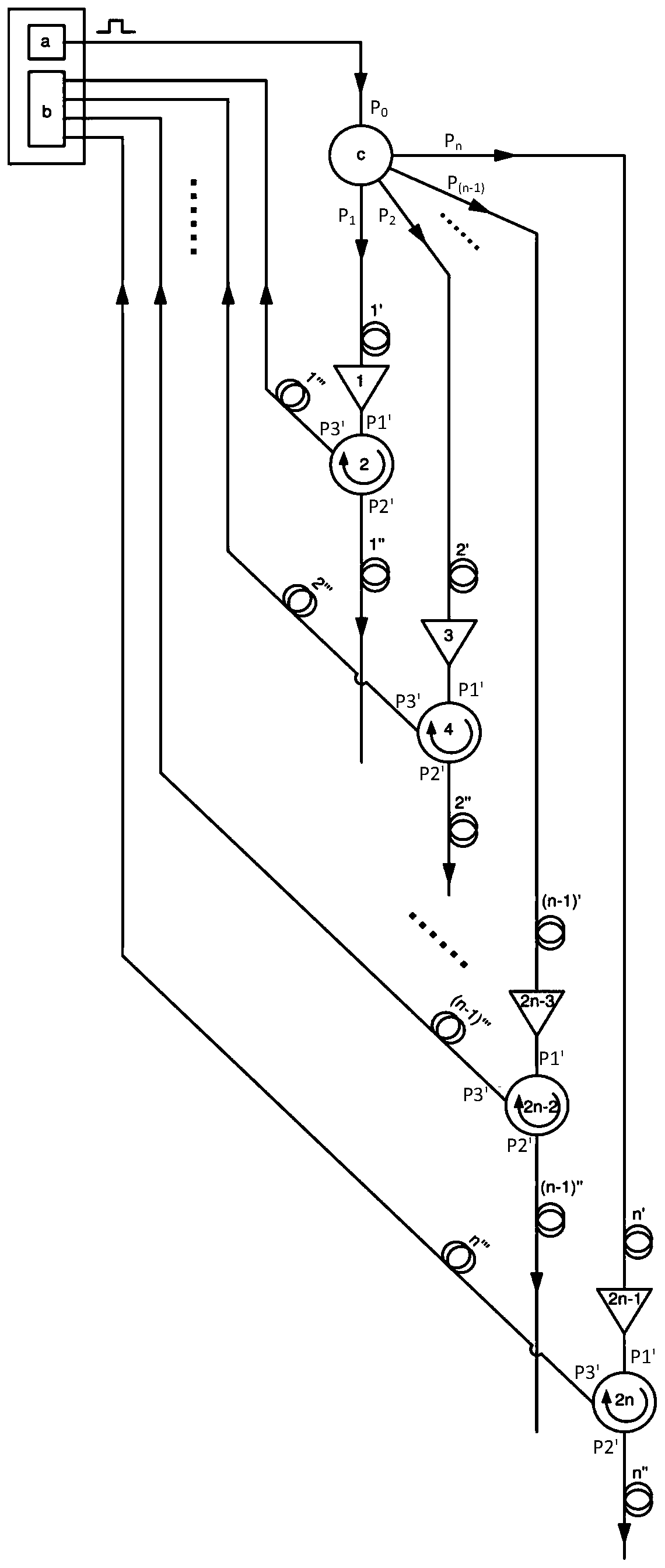
[0049] This embodiment provides a multi-channel telemetry optical fiber sensing system. When N circulators are arranged in a parallel structure: a splitter is also included; the 1' port of the splitter is used as an input terminal and a pulse light source System connection, the splitter also has N ports as output ports, and they are respectively connected to the 1 port of a corresponding circulator, the 2 port of the circulator is connected to the sensing fiber, and the 3 port is connected to the phase resolution through the Nth detection fiber. Tune the module connection. In addition, it also includes N fiber amplifiers and N delay fibers; port 1 of the Nth circulator is connected to the Nth output port of the splitter through the Nth fiber amplifier and the Nth delay fiber in sequence.

[0050] The working principle of the multi-channel telemetry optical fiber sensing system using parallel circulator structure is as follows:

[0051] Step 1, mixed light transmission:

[00...


PUM


Abstract

The invention discloses an optical fiber sensing system for multi-channel remote measurement, which comprises a pulse light source system and a phase demodulation module, wherein the pulse light source system is in communication connection with the phase demodulation module through an optical cable. The optical fiber sensing system also comprises N circulators, and N is a positive integer larger than or equal to 2; the N circulators are sequentially arranged in parallel or in series along the transmission direction of the optical cable; for each circulator, the end 1 of the circulator is usedfor inputting a pulsed light signal; the end 2 of each circulator is connected to a sensing optical fiber, a Rayleigh scattering light signal is generated in the transmission process of a pulsed lightsignal through the sensing optical fiber, enters through the port 2 of each circulator in the reverse direction of the transmission direction of the pulsed light signal, is output from the port 3, and finally enters the phase demodulation module through a detection optical fiber. The circulator is combined with the sensing optical fiber, and the repetition frequency of the original limit opticalpulse signal can be improved by N times, so that the upper limit of the detection phase conversion signal is improved by N times, and the pulse light with high repetition frequency can be used on thepremise of long-distance detection.

Description

technical field [0001] The invention relates to the technical field of optical fiber sensing, in particular to a multi-channel telemetry optical fiber sensing system and method. Background technique [0002] With the continuous progress of optical fiber technology, optical fiber sensing technology has been applied and developed in many fields. Among them, distributed optical fiber sensing is unique in sensing technology. It integrates transmission and sensing, and can realize high-density fully distributed measurement of temperature, strain, vibration, and sound waves up to hundreds of kilometers. It has irreplaceable advantages. , so it is widely used. In the traditional distributed vibration sensing system, when the sensing fiber is subjected to a vibration signal of a certain frequency, the signal can be demodulated by detecting the phase change of the back Rayleigh scattered light signal light received by the vibration in the sensing fiber. [0003] In the traditional ...

Claims


Application Information

Patent Timeline
Patent Type & Authority Applications(China)
IPC IPC(8): G01H9/00
CPCG01H9/006
Inventor 冉曾令王文郁
Owner UNIV OF ELECTRONICS SCI & TECH OF CHINA
Why Eureka
Try Eureka