Compact broadband filtering antenna based on cross coupling structure and MIMO antenna thereof

A technology of cross-coupling and filtering antennas, which is applied in the directions of antenna arrays, antennas, and slot antennas that are energized separately. It can solve the problems of large size, limited number of antennas, and large filter antenna unit size, and achieve small size, improved suppression, and The effect of bandwidth

Active Publication Date: 2020-06-16
UNIV OF ELECTRONICS SCI & TECH OF CHINA
View PDF13 Cites 20 Cited by
  • Summary
  • Abstract
  • Description
  • Claims
  • Application Information

AI Technical Summary

Problems solved by technology

The edge spacing of the MIMO antenna elements composed of it is 0.15λ L (λ L is the wavelength corresponding to the center frequency of the low frequency band), and due to the large size of a single filter antenna, it is about 0.51λ L ×0.63λ L / 0.7λ H ×0.87λ H (λ H is the wavelength corresponding to the center frequency of the high frequency band), so the number of antennas that can be placed in a certain space is limited
[0004] In 2018, H.W.Deng et al published a paper titled "Closely spaced broadband MIMO differential filtering slotline antenna With CM suppression " article, using the gap on the floor as the radiation unit, while using the dual-mode resonator as the feed structure, to achieve a filter antenna with better out-of-band rejection, the antenna bandwidth is 25%, the gain is 3.3dBi, the antenna unit The edge distance is 0.05λ 0 (λ 0 is the wavelength corresponding to the center frequency), the isolation is 16dB, but the size of the filter antenna unit is still large, close to λ 0 ×λ 0
[0005] In 2019, J.F. Qian et al published a paper entitled "A wide stopband filtering patch antenna and its application in MIMO system " article, using parallel coupled lines as the feed structure, designed a filter antenna with high-order harmonic suppression, the gain is 2.59dBi, and the size of the filter antenna unit is about 0.4λ 0 ×0.4λ 0 , when the MIMO antenna element edge spacing is 0.098λ 0 , the isolation is 26.5dBi, but the working bandwidth of the antenna is only 3.2%
[0006] With the development of massive MIMO systems towards compactness and miniaturization, it is difficult for filter antennas based on the above technologies to meet the requirements of bandwidth and size at the same time

Method used


Image

  • Compact broadband filtering antenna based on cross coupling structure and MIMO antenna thereof
  • Compact broadband filtering antenna based on cross coupling structure and MIMO antenna thereof
  • Compact broadband filtering antenna based on cross coupling structure and MIMO antenna thereof

Examples


Embodiment 1

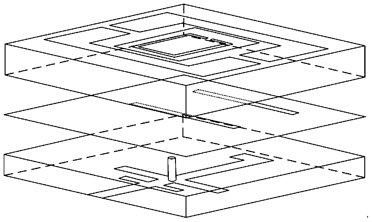
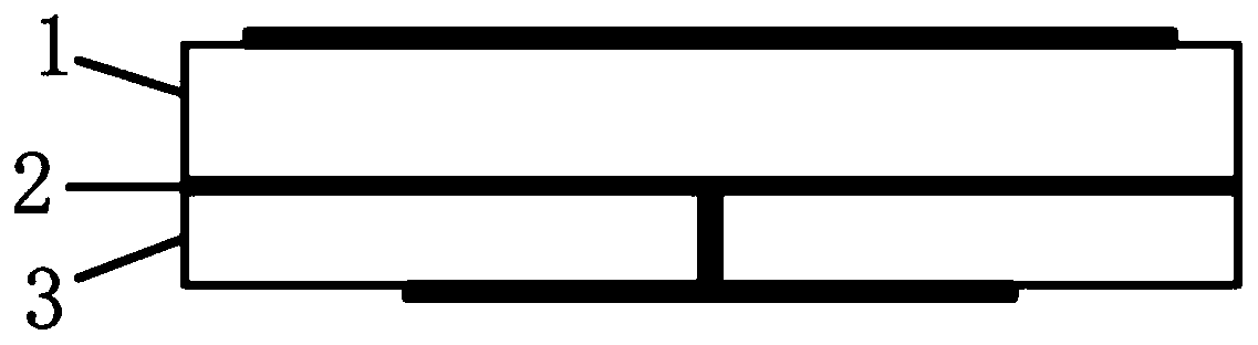
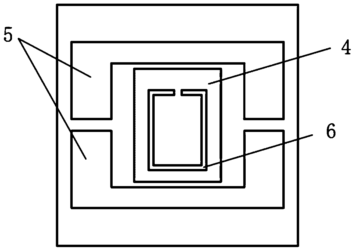
[0043] This embodiment provides a miniaturized broadband filter antenna based on a cross-coupling structure, the overall structure of which is shown in figure 1 As shown, the side view is as figure 2 As shown, it includes a first dielectric substrate 1, a metal floor 2, and a second dielectric substrate 3 that are the same size and closely adhered from top to bottom. The top view of the metal layer on the upper surface of the first dielectric substrate 1 is as image 3 As shown, a rectangular metal patch 4 and two U-shaped parasitic patches 5 are arranged at the center of the upper surface, which together serve as the radiation structure of the antenna; the two U-shaped parasitic patches 5 have opposite openings and are placed symmetrically around the rectangular metal patch 4 ; The rectangular metal patch 4 is etched with a split ring gap 6, and the opening of the split ring gap 6 faces upward. The top view of metal floor 2 is as Figure 4 As shown, there are two parallel slit...

Embodiment 2

[0053] A compact broadband MIMO filter antenna based on a cross-coupling structure. The unit described in the first embodiment is used as the unit antenna, and two by two orthogonally placed to form a 2×2 MIMO antenna. Its structure is as follows Figure 14 As shown, the edge spacing of adjacent microstrip feed structures is 1.7mm (0.028λ 0 ).

[0054] The MIMO filter antenna is simulated and analyzed, and the simulation results are as follows Figure 15 As shown, the isolation between antenna elements is within the working frequency band (|S 11 | Figure 16 As shown, it is lower than 0.06 in the working frequency band.


PUM


Abstract

The invention discloses a miniaturized broadband filtering antenna based on a cross coupling structure and a compact MIMO filtering antenna formed by the miniaturized broadband filtering antenna, which belong to the technical field of microwave antennas. The filtering antenna comprises a first dielectric substrate, a metal floor and a lower-layer second dielectric substrate which have the same size and are tightly attached to one another. The center of the upper surface of the first dielectric substrate is provided with a rectangular metal patch and two U-shaped parasitic patches surrounding the rectangular metal patch. The upper surface of the second dielectric substrate is a metal floor with two gaps, and the lower surface of the dielectric substrate is in a terminal bending open-circuitmicrostrip feed structure with two transverse branches and short-circuit nails. The filtering antenna is used as a unit to form a 2 * 2 MIMO antenna. The MIMO filtering antenna provided by the invention is compact in structure, and has obvious advantages in bandwidth, size and filtering performance.

Description

Technical field [0001] The invention belongs to the technical field of microwave antennas, and specifically relates to a miniaturized broadband filter antenna and a compact MIMO filter antenna based on a cross-coupling structure. Background technique [0002] The filter antenna integrates the filter and the antenna together, which not only has radiation and filtering characteristics at the same time, but also has a compact structure. If it is applied to a massive MIMO system, not only the communication performance of the system can be improved, but also the miniaturization of the system can be better realized. [0003] In recent years, domestic and foreign scholars have conducted research on filter antennas and their applications in MIMO systems. In 2017, XYZhang et al. published a paper titled "Low-Profile Dual-Band Filtering Patch Antenna and Its on IEEE Trans. Antennas Propag. (vol. 65, no. 1, pp. 103-113, Jan. 2017). "Application to LTE MIMO System" article uses a microstrip ...

Claims


Application Information

Patent Timeline
Patent Type & Authority Applications(China)
IPC IPC(8): H01Q1/22H01Q1/38H01Q13/10H01Q1/48H01Q21/06
CPCH01Q1/22H01Q1/38H01Q1/48H01Q13/10H01Q21/064
Inventor 陈冰洁杨雪松
Owner UNIV OF ELECTRONICS SCI & TECH OF CHINA
Why Eureka
Try Eureka