Passive three-balanced frequency converter

A frequency converter, balanced technology, applied in the field of passive three-balanced frequency converter, can solve the problems of reducing the operating frequency range of the diode loop, it is difficult to balance signal transmission and working conditions, and cannot meet the requirements of low-loss frequency conversion, etc., to achieve a simple structure , Good clutter filtering, small footprint

Active Publication Date: 2012-10-03
NANJING MILEWEI CORP
View PDF4 Cites 4 Cited by
  • Summary
  • Abstract
  • Description
  • Claims
  • Application Information

AI Technical Summary

Problems solved by technology

Since this frequency converter design relies on two diode loops to realize the three-balanced and symmetrical frequency conversion function, it has the following three insurmountable problems: 1) The interconnection of the two diodes requires a long transmission line, resulting in large Loss and parasitic effects reduce the operating frequency range in which the diode loop can effectively convert frequency; 2) Since this design needs to drive two secondary loops with a total of four pairs of double-balanced differential signals from the input and local oscillator baluns, and it needs to be driven from a side-derived output signal to the output balun
In this way, it is difficult to maintain symmetrical and balanced signal transmission and working conditions. At the same time, the crossover of multiple circuits produces parasitic coupling, so that the characteristics of the three-balanced operation are only established at lower frequencies, which destroys the higher isolation produced by the symmetrical balanced working principle.
3) Due to the need to drive two double loops consisting of 8 diodes in total, the working power required by the local oscillator source is also very large, and the frequency conversion loss is very high
When the initial frequency of the required output frequency range is very high, and its range overlaps with the input frequency range, this solution cannot meet the requirements of low-loss frequency conversion, and the working power required by the local oscillator is also very large

Method used


Image

  • Passive three-balanced frequency converter
  • Passive three-balanced frequency converter
  • Passive three-balanced frequency converter

Examples


Embodiment Construction

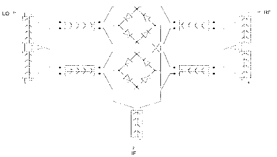
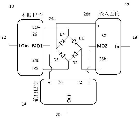
[0022] Such as figure 2, The cathodes and anodes of the four diodes D1, D2, D3, and D4 are connected end to end in turn to form a closed loop. Among the three signal conversion baluns, the local oscillator balun 10 is provided with four ports: an input terminal 22 connected to the local oscillator signal, two balanced differential signal output terminals 24a (LO+) and 24b ( LO-) and an in-phase signal output terminal 26, the in-phase signal output terminal is in the middle position of the two symmetrical balanced differential signal output terminals, according to the required local oscillator frequency and output frequency, it is relative to the two balanced differential signal output terminals. The signal output terminal belongs to the common point MO1 of virtual zero potential. The input balun 12 has four ports: an input terminal 18 connected to the frequency-converted signal, two balanced differential signal output terminals 28a and 28b with the same amplitude but opposit...


PUM


Abstract

The invention discloses a passive three-balanced frequency converter which comprises a closed loop as well as a local oscillation Balun, an input Balun and an output Balun which are signal converting Baluns, wherein the closed loop is formed by sequentially connecting cathodes and anodes of four diodes end to end; the local oscillation Balun and the input Balun are both provided an input end, two balance differential signal output ends with same amplitude but and opposite phases, and an in-phase signal output end. The output Balun is provided with two balance differential signal input ends with same amplitude and opposite phases and an output end. In the four-diode closed loop, two diagonal points are respectively connected with the two balance differential signal output ends of the local oscillation Balun, while the other two diagonal points are respectively connected with the two balance differential signal output ends of the input Balun; and the in-phase signal output end of the local oscillation Balun and the in-phase signal output end of the input Balun are respectively connected with the two input ends of the balance differential signal of the output Balun.

Description

technical field [0001] The invention relates to a passive frequency converter of a radio frequency, microwave, and millimeter wave system, in particular to a passive triple-balanced frequency converter, which can realize frequency conversion between arbitrarily set frequency bands. Background technique [0002] Passive frequency converters have been widely used in radio frequency, microwave and millimeter wave systems. They are key components of transceiver systems, and are generally used to realize intermediate frequency frequency signals of digital / analog fundamental frequency circuits and radio frequency microwave millimeter waves that can be transmitted wirelessly. An important function of conversion between high-frequency signals such as waves and other frequency bands. However, with the rapid development of wireless communication, the wireless operating bandwidth required by the same transceiver is increasing day by day, and the operating frequency of the intermedi...

Claims


Application Information

Patent Timeline
Patent Type & Authority Applications(China)
IPC IPC(8): H03D7/14
Inventor 姜鑫
Owner NANJING MILEWEI CORP
Why Eureka
Try Eureka