Automatic welding device for anchor backing plate and automatic welding method for anchor backing plate
A technology of automatic welding and anchor backing plate, which is applied in the direction of welding accessories, electrode support devices, and electrode clamp support devices, etc., which can solve the problems of human health and personal safety, delay of construction period, low processing efficiency, etc., and solve the problem of welding The effect of uneven quality, controllable weld precision and high welding efficiency
- Summary
- Abstract
- Description
- Claims
- Application Information
AI Technical Summary
Problems solved by technology
Method used
Image

Examples
Embodiment 1
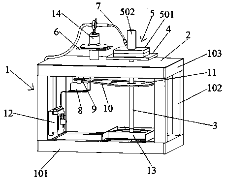
[0021] refer to figure 1 , the embodiment of the present invention proposes an automatic welding device for anchor backing plates, comprising: a frame 1, a fixed table 6 and a motor 8; A rotating shaft 3 is provided for vertical rotation in the frame 1, and the upper part of the rotating shaft 3 extends out of the through hole on the workbench 2. The upper part of the rotating shaft 3 is provided with a horizontal platform seat 4, which is located above the workbench 2. The horizontal platform seat 4 is used to place Anchor backing plate 5; fixed platform 6 is arranged on workbench 2, and gas shielded welding torch 7 is directly or indirectly fixed on fixed platform 6, and the end of gas shielded welding torch 7 faces horizontal platform seat 4; motor 8 is arranged in frame 1, The motor 8 drives the rotating shaft 3 to rotate through the transmission mechanism.
[0022] Frame 1 can be made by welding existing angle steel materials at the construction site to ensure that the t...
Embodiment 2
[0024] refer to figure 1 , on the basis of Embodiment 1, the transmission mechanism includes a driving sprocket 9, a transmission chain 10 and a driven sprocket 11, the driving sprocket 9 is arranged on the main shaft of the motor 8, the driven sprocket 11 is arranged on the rotating shaft 3, and the transmission chain 10 is sleeved between driving sprocket 9 and driven sprocket 11.
[0025] The diameter of driven sprocket 11 is greater than the diameter of driving sprocket 9, can reduce the rotational speed of rotating shaft 3 to motor 8, and driving sprocket 9 and driven sprocket 11 are thinner, and quality is also light, and rotating shaft when motor 8 starts or stops 3 will not have a large inertia, will not affect the stability of the frame 1, and then try not to affect the welding quality.
Embodiment 3
[0027] refer to figure 1 , on the basis of Embodiment 2, also includes a controller 12, the controller 12 is connected with the motor 8 signal, and controls the start, stop and rotation speed of the motor 8.
[0028] The controller 12 is arranged between the power supply and the motor 8. In addition to controlling the start and stop of the motor 8, it can also adjust the rotating speed of the motor 8, and then adjust the rotation speed of the rotating shaft 3 and the horizontal platform base 4, so that the horizontal platform base 4 can be placed The anchor plate 5 can be rotated at different speeds to meet different welding requirements.
PUM
 Abstract
Description
Claims
Application Information
 - R&D
- Intellectual Property
- Life Sciences
- Materials
- Tech Scout
- Unparalleled Data Quality
- Higher Quality Content
- 60% Fewer Hallucinations
Browse by: Latest US Patents, China's latest patents, Technical Efficacy Thesaurus, Application Domain, Technology Topic, Popular Technical Reports.
© 2025 PatSnap. All rights reserved.Legal|Privacy policy|Modern Slavery Act Transparency Statement|Sitemap|About US| Contact US: help@patsnap.com