Ship straight wing stabilization system
A straight-wing, ship technology, applied in the field of ship straight-wing anti-rolling system, can solve the problem of difficulty in large-scale gyro anti-rolling device, and achieve the effects of saving ship space, high propulsion efficiency, and convenient installation.
- Summary
- Abstract
- Description
- Claims
- Application Information
AI Technical Summary
Problems solved by technology
Method used
Image
Examples
Embodiment 1
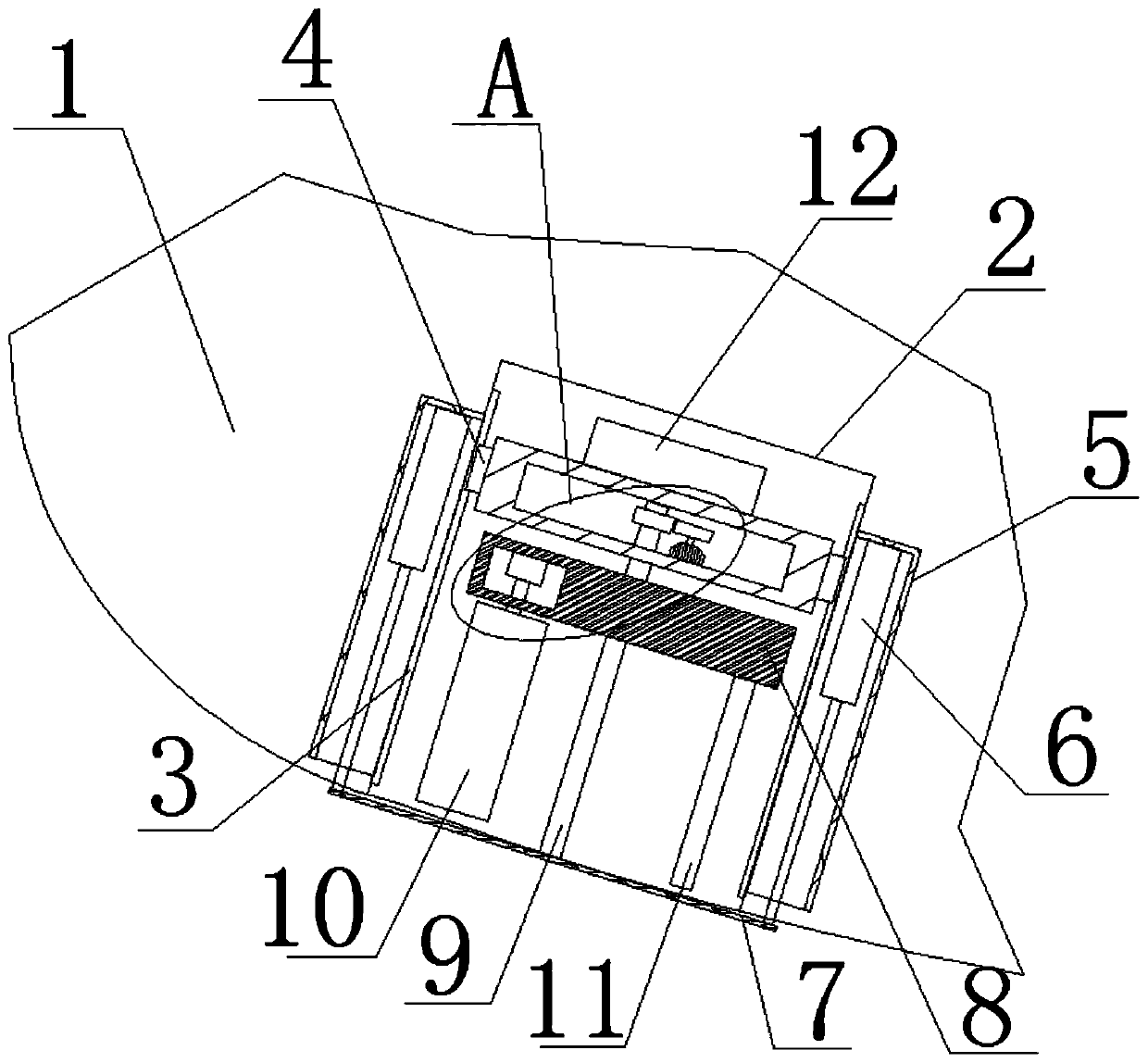
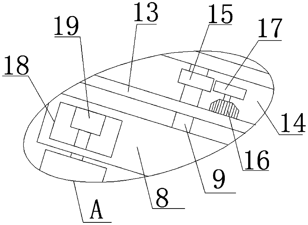
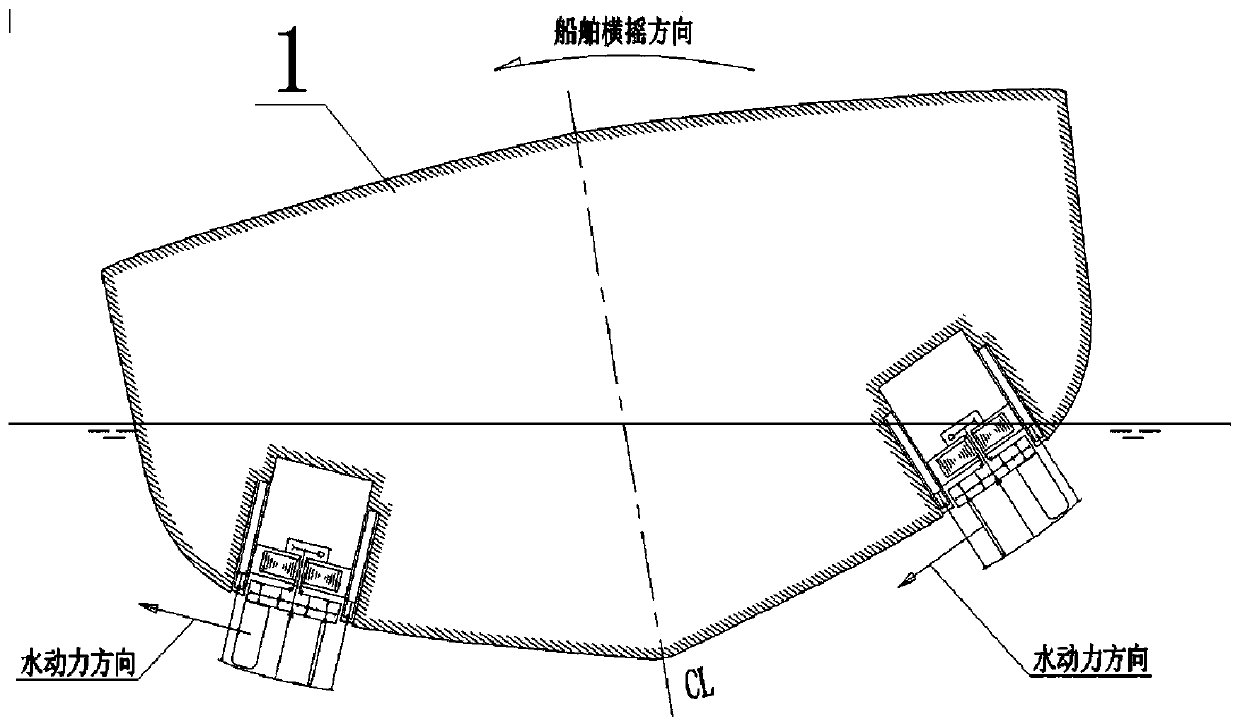
[0027] refer to Figure 1-4 , the straight-wing anti-rolling system of a ship includes a hull 1, and a placement groove 2 is provided on one side of the hull 1, and a straight-wing thruster is installed in the placement groove 2, and the straight-wing thruster includes a base 13, and the top of the base 13 is fixedly installed There is a rotor angle controller 12, a cavity 14 is provided on the base 13, a transmission shaft 9 is installed on the top inner wall of the cavity 14, and the bottom of the transmission shaft 9 extends to the outside of the base 13, and the top of the transmission shaft 9 is fixed. The first gear 15 is socketed, and one side of the first gear 15 is provided with a rotating motor 16 fixedly installed on the inner wall of the bottom of the cavity 14, and a second gear 17 is fixedly installed on the output shaft of the rotating motor 16, and the second gear 17 meshes with the first gear 15, the transmission shaft 9 is fixedly sleeved with the rotating di...
Embodiment 2
[0033] refer to Figure 1-4 , the straight-wing anti-rolling system of a ship includes a hull 1, and a placement groove 2 is provided on one side of the hull 1, and a straight-wing thruster is installed in the placement groove 2, and the straight-wing thruster includes a base 13, and the top of the base 13 is fixedly installed There is a rotor angle controller 12, which is used to control the angle of the rotor. A cavity 14 is provided on the base 13, and a transmission shaft 9 is installed on the top inner wall of the cavity 14, and the bottom of the transmission shaft 9 extends to the outside of the base 13. , the transmission shaft 9 is fixedly sleeved with a first gear 15, and one side of the first gear 15 is provided with a rotating motor 16 fixedly installed on the inner wall at the bottom of the cavity 14, and the rotating motor 16 can also be combined with a frequency converter and an asynchronous motor A second gear 17 is fixedly installed on the output shaft of the r...
PUM
 Abstract
Description
Claims
Application Information
 - R&D
- Intellectual Property
- Life Sciences
- Materials
- Tech Scout
- Unparalleled Data Quality
- Higher Quality Content
- 60% Fewer Hallucinations
Browse by: Latest US Patents, China's latest patents, Technical Efficacy Thesaurus, Application Domain, Technology Topic, Popular Technical Reports.
© 2025 PatSnap. All rights reserved.Legal|Privacy policy|Modern Slavery Act Transparency Statement|Sitemap|About US| Contact US: help@patsnap.com


