
A Combined Turbine Structure with Hollow Nozzle Blades

A nozzle blade and combined technology, which is applied in the field of combined turbine structure with hollow nozzle blades, can solve the problems of affecting the safety and reliability of the unit, reducing the service life of the blades, and low aerodynamic efficiency, and achieving the phenomenon of not easy resonance, Improve service life and uniform air intake

Active Publication Date: 2022-04-19
INST OF ENGINEERING THERMOPHYSICS - CHINESE ACAD OF SCI
View PDF0 Cites 0 Cited by
  • Summary
  • Abstract
  • Description
  • Claims
  • Application Information

AI Technical Summary

Problems solved by technology

[0003] First of all, for a turbine unit with high inlet pressure and high temperature, generally the inlet volume flow rate of the first expansion stage is also small. If the first stage adopts an axial-flow impeller structure, the height of the blades will be small, which will This leads to large energy loss and low aerodynamic efficiency. Designers generally adopt partial air intake structure schemes to increase the blade height of the first stage, but the partial air intake structure will cause the first stage rotor blades to be affected by the periodic air flow at the nozzle outlet. The strong excitation force brings great challenges to the design of the structure, strength and service life of the first-stage moving blade
In the application field of steam turbines, the first expansion stage is often called the regulating stage, and the blades often vibrate and break during operation, which seriously affects the safety and reliability of the unit
[0004] In addition, steam turbines for thermal power generation are currently developing towards higher inlet temperature (above 620°C) and pressure (above 31MPa) to further improve system efficiency and reduce coal consumption. , The material of the blade puts forward higher requirements, and the first stage nozzle blade often needs to be cooled by additional medium and low temperature steam, so that the imported high temperature steam will not damage the nozzle blade or reduce the service life of the blade

Method used


Image

  • A Combined Turbine Structure with Hollow Nozzle Blades
  • A Combined Turbine Structure with Hollow Nozzle Blades
  • A Combined Turbine Structure with Hollow Nozzle Blades

Examples


Embodiment Construction

[0037] In order to make the objectives, technical solutions and advantages of the present invention clearer, the technical solutions in the embodiments of the present invention will be described in more detail below in conjunction with the drawings in the embodiments of the present invention. In the drawings, the same or similar reference numerals denote the same or similar elements or elements having the same or similar functions throughout. The described embodiments are some, but not all, embodiments of the invention. The embodiments described below by referring to the figures are exemplary and are intended to explain the present invention and should not be construed as limiting the present invention. Based on the embodiments of the present invention, all other embodiments obtained by persons of ordinary skill in the art without creative efforts fall within the protection scope of the present invention. The structure and technical solutions of the present invention will be ...


PUM


Abstract

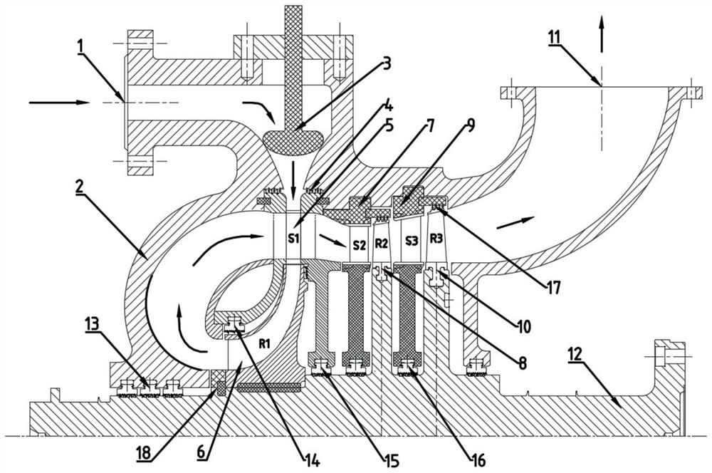
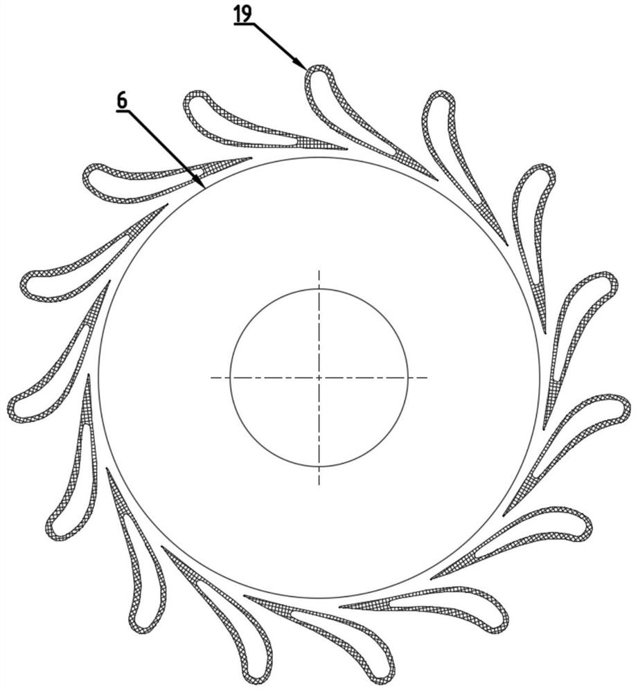
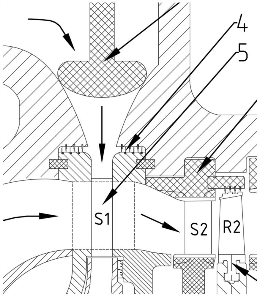
The invention relates to a combined turbine structure with hollow nozzle blades, comprising at least one centripetal turbine and at least one stage of axial flow turbine arranged downstream of the centripetal turbine, the nozzle blades of the centripetal turbine are hollow structures , After the high-pressure air flow passes through the regulating valve set in the cylinder inlet passage, it first enters the centripetal turbine to do work, and the exhaust gas of the impeller turns and passes through the axial air flow channel of the nozzle blade to enter the downstream turbine to continue to do work. The invention adopts the centripetal impeller in the first stage, which can meet the design requirements of small volume flow and large enthalpy drop, rapidly reduce the temperature and pressure of the working medium, and easily realize the whole-circle air intake of the nozzle or increase the partial air intake of the nozzle, so as to Improve the aerodynamic efficiency of the turbine and reduce the exciting force of the air flow on the impeller; in addition, when the outlet gas of the centripetal turbine passes through the axial air flow channel, it can cool the nozzle blades and reduce the high temperature resistance requirements of the blade materials. Increase the service life of the blades.

Description

technical field [0001] The invention belongs to the technical field of turbomachinery, and relates to a combined turbine structure, in particular to a combined turbine structure with hollow nozzle blades, which can meet the small volume flow rate by adopting a centripetal impeller in the first stage. , large enthalpy drop design requirements, quickly reduce the temperature and pressure of the working medium, easy to realize the nozzle full-circle air intake or increase the partial air intake of the nozzle, so as to improve the aerodynamic efficiency of the turbine and reduce the air flow excitation suffered by the impeller In addition, when the outlet gas of the centripetal impeller passes through the hollow part of the nozzle blade, the blade can be cooled, reducing the requirement for high temperature resistance of the blade material and improving the service life of the blade. Therefore, for the technical requirements of small volume flow rate and high intake air temperatur...

Claims


Application Information

Patent Timeline
Patent Type & Authority Patents(China)
IPC IPC(8): F01D9/04F01D9/02F01D1/02
CPCF01D9/04F01D9/042F01D9/026F01D1/02
Inventor 朱阳历陈海生李辉李文张雪辉胡东旭王星
Owner INST OF ENGINEERING THERMOPHYSICS - CHINESE ACAD OF SCI
Learn More