Rotary tribological behavior simulation test bed for realizing vibration decoupling

A technology for simulating test benches and tribology, which is applied in the field of friction and vibration, can solve problems such as the inability to accurately study the tribological behavior of the friction pair interface, and achieve the effects of reducing motion transmission paths, response spans, and response smooth controllability

Active Publication Date: 2020-06-19
SOUTHWEST JIAOTONG UNIV
View PDF10 Cites 12 Cited by
  • Summary
  • Abstract
  • Description
  • Claims
  • Application Information

AI Technical Summary

Problems solved by technology

[0004] Aiming at the problem that the vibration interference signal caused by the non-friction interface will be superimposed on the self-excited vibration of the interface friction in the existing tribological behavior simulation test, and the problem that the tribological behavior of the friction pair interface cannot be accurately studied, the present invention provides a rotating The purpose of the tribological behavior simulation test bench is to realize the complete decoupling of the vibration interference signal generated by the non-friction interface and the self-excited vibration signal of the interface friction by using the air bearing with frictionless contact motion, so as to collect the self-excited vibration of the interface friction more accurately The generated characteristic parameters are used to accurately study the influencing factors and evolution laws of the tribological behavior of mechanical systems

Method used


Image

  • Rotary tribological behavior simulation test bed for realizing vibration decoupling
  • Rotary tribological behavior simulation test bed for realizing vibration decoupling
  • Rotary tribological behavior simulation test bed for realizing vibration decoupling

Examples


Embodiment Construction

[0028] All features disclosed in this specification, or steps in all methods or processes disclosed, may be combined in any manner, except for mutually exclusive features and / or steps.

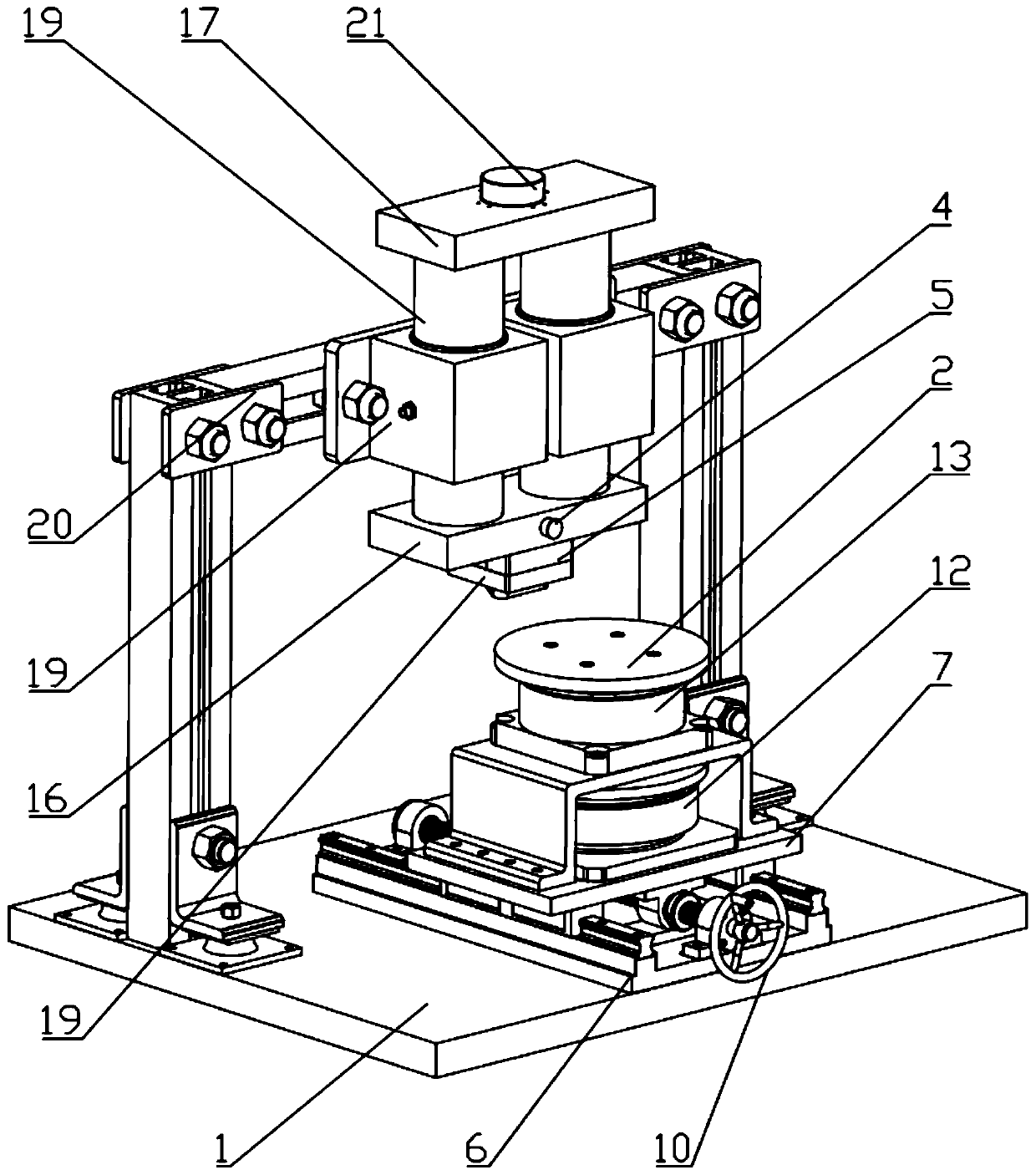
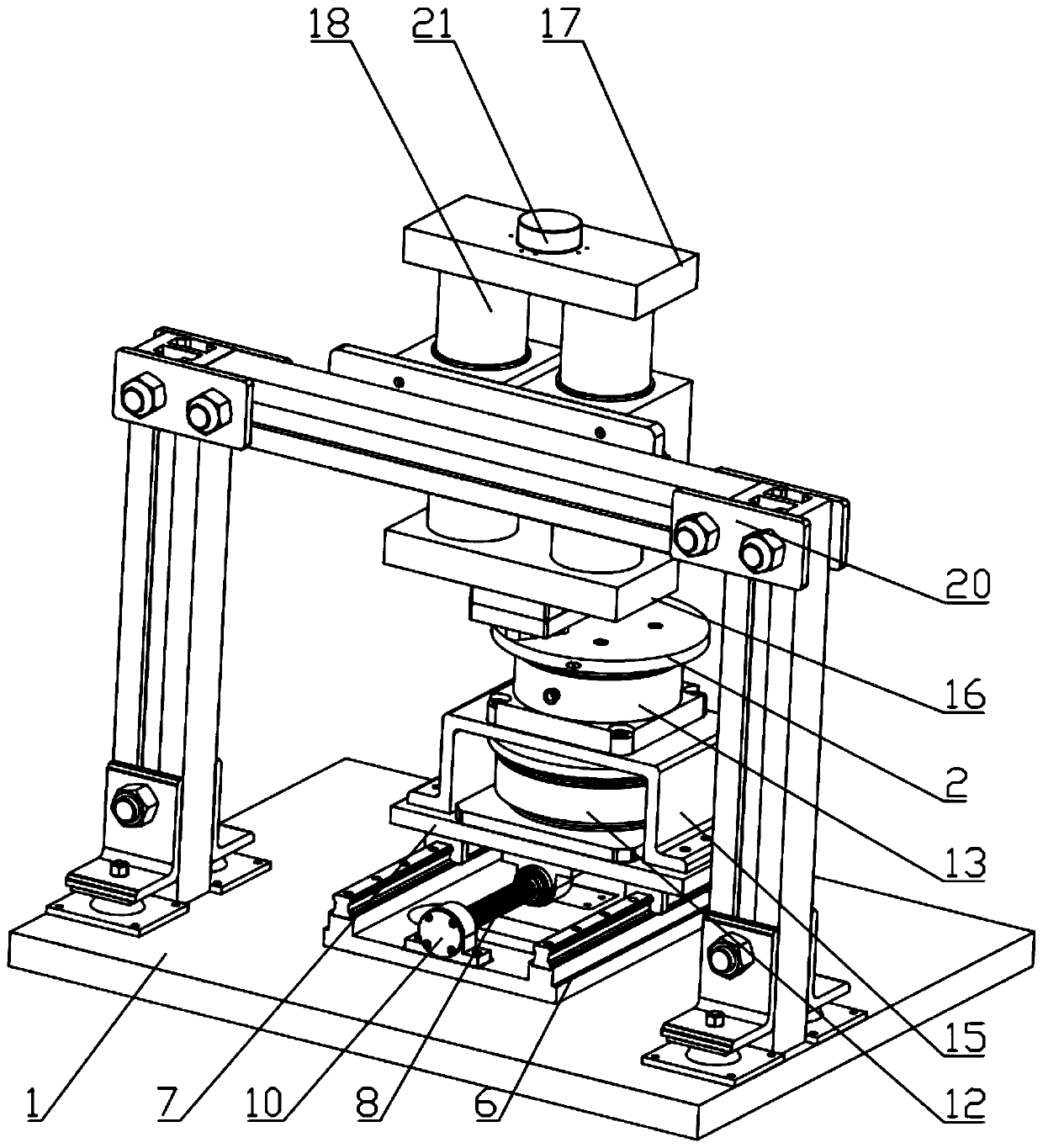
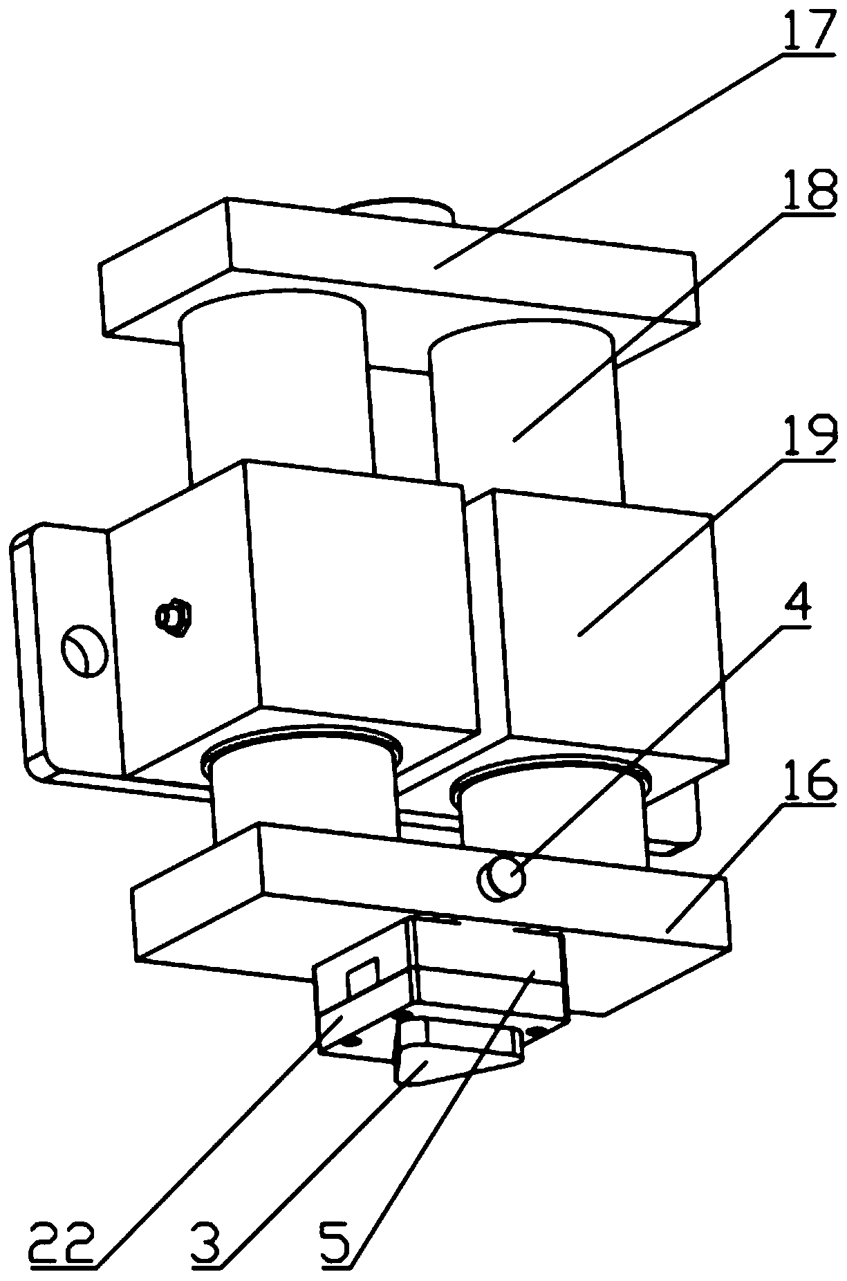
[0029] Combine below figure 1 , figure 2 The present invention will be described in detail. A rotary tribological behavior simulation test bench that realizes vibration decoupling, including a test bench base 1, a lower friction sample 2 is arranged on the test bench base 1, and an upper friction sample 2 is arranged above the lower friction sample 2. Friction sample 3, a rotation system is provided between the lower friction sample 2 and the test bench base 1, and the upper friction sample 3 is connected with a loading system, and the loading system is provided with an acceleration sensor 4 and a three-way force sensor 5.

[0030] In the above scheme, the rotating system is fixed on the base 1 of the test bench, the lower friction sample 2 is set on the rotating system, the rotating syste...


PUM


Abstract

The invention discloses a rotary tribological behavior simulation test bed for realizing vibration decoupling. The test bed comprises a test bed base. A lower friction sample is arranged on the test bed base, an upper friction sample is arranged above the lower friction sample, a rotating system is arranged between the lower friction sample and the test bed base, the upper friction sample is connected with a loading system, and an acceleration sensor and a three-way force sensor are arranged on the loading system. The rotating system is arranged to drive the lower friction sample to rotate; the loading system is arranged to control the friction contact loads required by the upper friction sample and the lower friction sample; on the basis of the non-contact working principle of the air bearing, interference signals caused by structural resonance of a supporting device, vibration of a driving part and the like in a test and interface friction self-excited vibration signals are decoupled, so that influence factors of the interface tribology behavior of the rotary friction pair are researched and analyzed, and an evolution rule and a regulation and control method of the interface tribology behavior of the rotary interface are explored.

Description

technical field [0001] The invention belongs to the technical field of friction and vibration, and in particular relates to a rotary tribological behavior simulation test bench for realizing vibration decoupling. Background technique [0002] Friction is a very common phenomenon in daily life and engineering fields. For example, in practical applications such as machine tool processing systems, vehicle braking systems, and robot joint joint systems, there are parts that are in contact with each other and relatively moving. The contact of these parts The surface will thus generate friction, and exhibit different interfacial tribological behaviors and frictional self-excited vibrations. Strong friction self-excited vibration will increase the wear of parts, reduce the precision and reliability of mechanical equipment, lead to a greatly shortened service life, seriously affect the normal operation of equipment, and even cause serious safety accidents. Therefore, the friction s...

Claims


Application Information

Patent Timeline
Patent Type & Authority Applications(China)
IPC IPC(8): G01M13/00G01N19/02G01H17/00
CPCG01H17/00G01M13/00G01N19/02
Inventor 莫继良刘启昂范志勇项载毓周仲荣
Owner SOUTHWEST JIAOTONG UNIV
Why Eureka
Try Eureka