
Rotary machine vibration measurement method based on micro motion amplification

A rotating machinery and motion amplification technology, applied in the field of computer vision, can solve the problems that the laser vibrometer cannot be used for measurement of dynamic parts, cannot be fixed at one point, and small measurement distance, etc., to achieve high measurement efficiency and practical application value, fast measurement and the effect of fault damage localization advantage

Inactive Publication Date: 2020-06-19
智方达(天津)科技有限公司
View PDF5 Cites 10 Cited by
  • Summary
  • Abstract
  • Description
  • Claims
  • Application Information

AI Technical Summary

Problems solved by technology

[0003] However, the current non-contact measurement has also encountered technical bottlenecks. For example, the laser vibrometer is a relatively accurate non-contact measurement instrument, but for high-speed rotating components such as blades, disks, and shafts, the laser measurement point is in high-speed motion. , cannot be fixed at one point, which makes the laser vibrometer unable to be applied to the measurement of dynamic parts rotating at high speed
In addition, although the wireless sensor with the launch function can be attached to the rotating part for measurement, its mass is generally large, and even a lighter wireless sensor will bring a large eccentric inertial force to the rotating motion, making the measurement result inaccurate , even eccentricity will cause changes in its dynamic behavior, such as instability, etc.
Other non-contact sensors, such as eddy current sensors, need to leave a very small measurement distance at high-speed rotating parts, and the large vibration of high-speed rotating machinery will cause its interference collision
Therefore, other wireless sensors and measurement solutions have encountered technical bottlenecks

Method used


Image

  • Rotary machine vibration measurement method based on micro motion amplification
  • Rotary machine vibration measurement method based on micro motion amplification
  • Rotary machine vibration measurement method based on micro motion amplification

Examples


Embodiment Construction

[0027] The technical solutions in the embodiments of the present invention will be clearly and completely described below in conjunction with the accompanying drawings in the embodiments of the present invention. Obviously, the described embodiments are only some of the embodiments of the present invention, not all of them. Based on the embodiments of the present invention, all other embodiments obtained by persons of ordinary skill in the art without making creative efforts belong to the protection scope of the present invention.

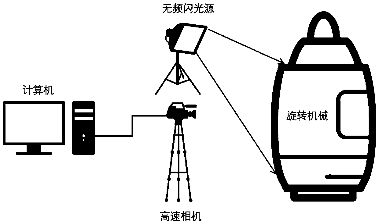
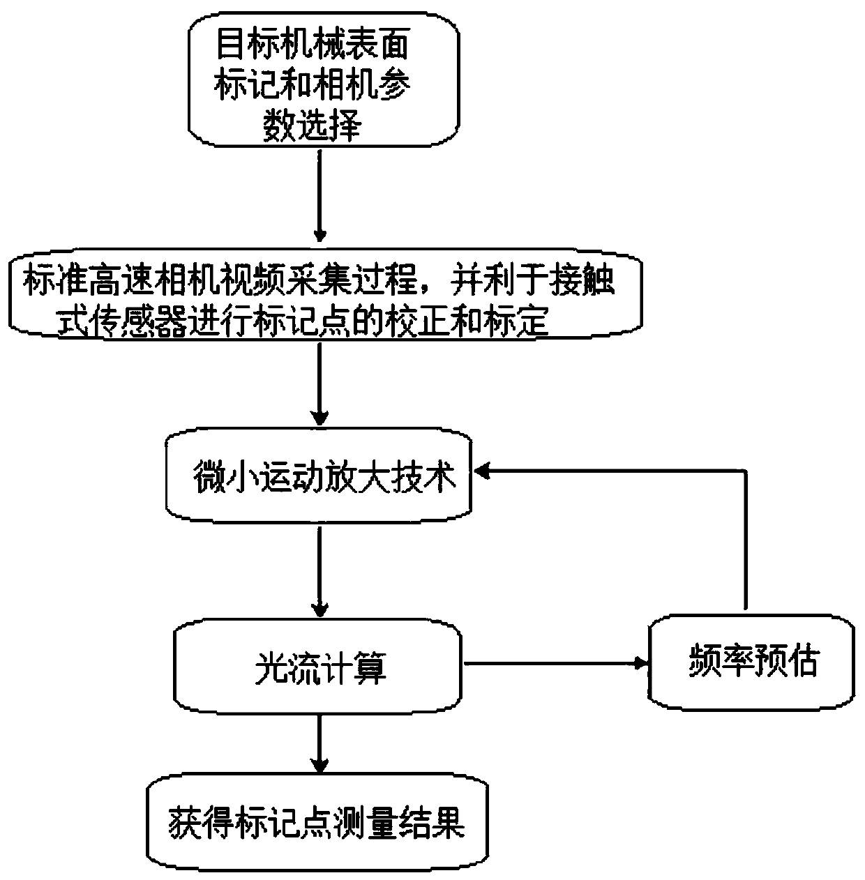
[0028] combine figure 1 with figure 2 , the present invention proposes a method for measuring vibration of rotating machinery based on micro-motion amplification, which specifically includes the following steps:

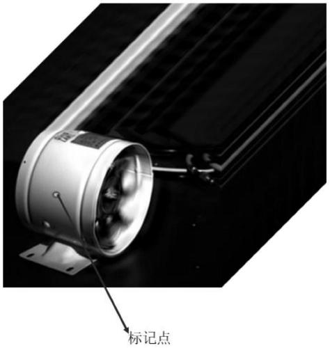
[0029] Step 1. Paste marking points on the surface of the rotating machinery, and perform high-contrast color processing on the background of the measuring rotating machinery, so as to achieve a high-contrast visual environment between ...


PUM


Abstract

The invention provides a rotary machine vibration measurement method based on micro motion amplification. The method comprises the steps that step 1, pasting mark points to the surface of a rotary machine; step 2, selecting parameters of a high-speed camera, and performing video acquisition by using the high-speed camera after the selection is completed; step 3, performing object motion amplification processing on an acquired high-speed video by adopting a micro motion amplification technology; step 4, performing optical flow calculation on the amplified high-speed video; step 5, obtaining a vibration frequency, a phase, an amplitude and an energy spectrum according to an optical flow calculation result; and step 6, obtaining a measurement result of the mark point. The method has the advantages of being high in reliability and precision, free of contact, easy to implement and the like.

Description

technical field [0001] The invention belongs to the fields of computer vision, mechanical dynamics and control and non-destructive testing technology, and in particular relates to a method for measuring vibration of rotating machinery based on micro-motion amplification. Background technique [0002] Rotating machinery is the core equipment in modern industry, and plays an important role as core equipment in the fields of vehicles, power engineering, petroleum, chemical industry, aviation, and aerospace. Fault diagnosis and condition monitoring of rotating machinery is a necessary means to detect early equipment failures and identify damage in time, and is an effective means to maintain the safe operation of rotating machinery equipment. However, the current vibration monitoring methods for rotating machinery mainly include contact measurement methods and non-contact measurement methods. Among them, the contact method needs to install sensing elements directly on the rotati...

Claims


Application Information

Patent Timeline
Patent Type & Authority Applications(China)
IPC IPC(8): G01M99/00G01M13/00G01H9/00
CPCG01H9/00G01M13/00G01M99/005
Inventor 杨天智金洋陈立群
Owner 智方达(天津)科技有限公司
Learn More