A method to detect co in porous media using ct technology 2 Diffusion method

A technology of porous media and CT technology, which is applied in the field of devices for detecting the dispersion of CO2 in porous media, which can solve the problems of dispersion coefficient deviation, inability to obtain porous media, and less dispersion process

Active Publication Date: 2018-01-26
DALIAN UNIV OF TECH
View PDF9 Cites 0 Cited by
  • Summary
  • Abstract
  • Description
  • Claims
  • Application Information

AI Technical Summary

Problems solved by technology

[0004] Currently for CO 2 CO in enhanced natural gas recovery technology 2 -CH 4 There are relatively few studies on the diffusion process, and the existing studies are mainly on the CO 2 -CH 4 Diffusion coefficient measurements, and the CO 2 -CH 4 The traditional research on the measurement of dispersion coefficient mainly stays in the gas analysis and measurement of the gas produced at the outlet of the experimental system, and then solves the dispersion coefficient and analyzes the dispersion process through the convective dispersion theory. The influence of the road effect and the inlet and outlet effect on the measurement of the dispersion coefficient in porous media, the obtained dispersion coefficient generally has a large deviation
In addition, visualization studies on the diffusion process are scarce, although some researchers have carried out CO 2 -CH 4 The visualization study of the dispersion process, but it mainly presents the macroscopic density distribution inside the core, neither can give the microscopic pore structure inside the porous medium, nor can it obtain the CO2 density in the porous medium. 2 -CH 4 Diffusion coefficient, its dispersion coefficient is also obtained according to the traditional method, including the overall diffusion coefficient including pipeline effect and inlet and outlet effects

Method used


Image

  • A method to detect co in porous media using ct technology  <sub>2</sub> Diffusion method
  • A method to detect co in porous media using ct technology  <sub>2</sub> Diffusion method
  • A method to detect co in porous media using ct technology  <sub>2</sub> Diffusion method

Examples


Embodiment Construction

[0021] The specific embodiments of the present invention will be described in detail below in conjunction with the technical solutions and accompanying drawings.

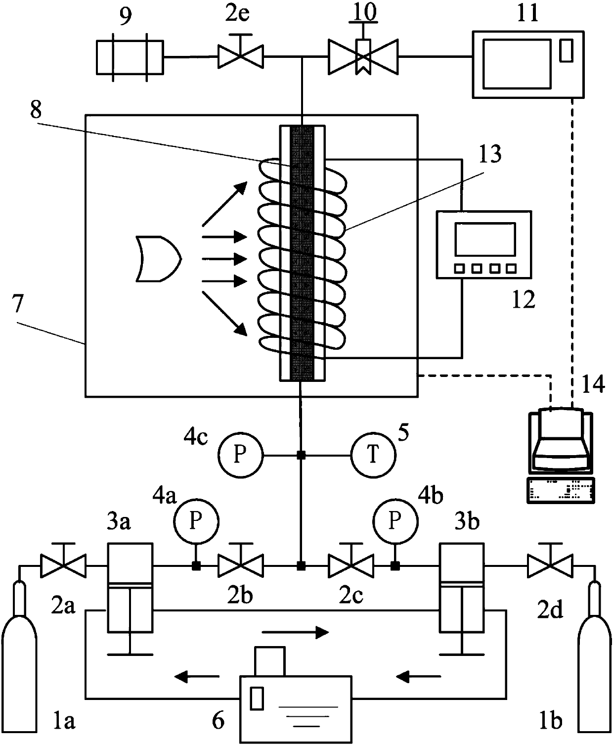
[0022] figure 1 Indicates a method for detecting CO in porous media using CT technology 2 The dispersion device mainly includes a CT system, a fluid injection system, a gas composition analysis system, and a data acquisition and processing system. The CT system is provided with a sand-filled core tube 8 made of polyetheretherketone (PEEK) in the micro-CT instrument 7, and the sand-filled core tube 8 is wrapped by a graphite heating band 13, and the graphite heating band 13 is connected to the electric circuit through a wire. Temperature control regulator 12; the inlet of the sand-filled core tube 8 is connected to the fluid injection system, and the outlet of the sand-filled core tube 8 is divided into two paths: one path is connected to the gas chromatograph 11 in the gas composition analysis system through the ba...


PUM


Abstract

The present invention belongs to the technical field of natural gas resource development and CO2 emission reduction, and is characterized in that: the device mainly includes a CT (computed tomography) system, a fluid injection system, a gas analysis system and a data acquisition and processing system, a high pressure resistant sand filling stone core tube is arranged in a CT instrument in the CT system, according to the method, CT is used for real-time measuring of density change of a fluid in a porous media, by combination of CO2-CH4 mixture state equation, concentration change distribution of the components in the porous media can be obtained, and on the basis of theory of convective diffusion, by use of finite difference method, the dispersion coefficient in the porous media can be directly obtained. The effects and benefits are that: the CT instrument can be used for nondestructive and real time measurement of micro-pore structure and density change of the fluid in the porous media for further obtaining the dispersion coefficient in the porous media, visually and quantitatively descript CO2-CH4 dispersion process in the porous media, and more accurately revealing the CO2-CH4 dispersion process rule in the porous media.

Description

technical field [0001] The invention belongs to natural gas resources development and CO 2 In the field of emission reduction technology, it specifically relates to a method for detecting CO in porous media using CT technology. 2 Apparatus and method of dispersion. Background technique [0002] Natural gas (mainly composed of CH 4 ) is a clean, efficient, and environmentally friendly high-quality energy, which is conducive to reducing pollutant emissions. Based on the needs of environmental protection and social development, my country's demand for natural gas is increasing year by year. At the same time, due to the extensive use of fossil fuels such as coal and oil, the main greenhouse gas CO in the atmosphere 2 Concentrations are increasing, causing global warming. Thus improving clean energy supply and reducing CO 2 Emissions became a concern. [0003] CO 2 Enhanced natural gas recovery technology, which refers to the injection of CO 2 To the bottom of the deplet...

Claims


Application Information

Patent Timeline
Patent Type & Authority Patents(China)
IPC IPC(8): G01N13/00
Inventor 张毅刘树阳宋永臣刘瑜刘卫国杨明军赵佳飞赵越超蒋兰兰李洋辉吕鹏飞李彤彤王路路
Owner DALIAN UNIV OF TECH
Why Eureka
Try Eureka