Automatic feeding and automatic turning-round magnetic material punching machine

A technology of magnetic materials and drilling machines, applied in boring/drilling, drilling/drilling equipment, metal processing, etc., can solve the problems of high labor costs, increased defect rate, low processing accuracy, etc., to reduce labor The effect of time and labor intensity, avoiding product missing corners, and avoiding loss of precision

Pending Publication Date: 2020-06-23
宁波市江北宁科金创机械制造有限公司
View PDF0 Cites 1 Cited by
  • Summary
  • Abstract
  • Description
  • Claims
  • Application Information

AI Technical Summary

Problems solved by technology

[0003] 1. The processing accuracy is low. During the second processing, the product cannot be guaranteed to be carried out in the same environment as the first processing (such as: the same processing equipment, the same processing tool), so the processing accuracy cannot be guaranteed
[0004] 2. The processing efficiency is low, one end needs to be punched first, and the other end needs to be completed by another equipment
[0005] 3. Increase the defect rate. During the collection and screening of secondary materials, because magnetic materials are brittle and hard, it is easy to cause material chipping and fracture, thereby increasing the defect rate of products.
[0006] 4. The labor cost is high, and workers are required to collect and screen secondary materials and reload materials

Method used


Image

  • Automatic feeding and automatic turning-round magnetic material punching machine
  • Automatic feeding and automatic turning-round magnetic material punching machine
  • Automatic feeding and automatic turning-round magnetic material punching machine

Examples


Embodiment Construction

[0036] Embodiments of the present invention will be further described in detail below in conjunction with the accompanying drawings.

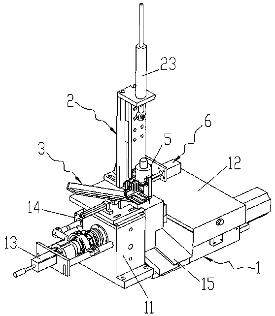
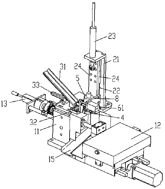
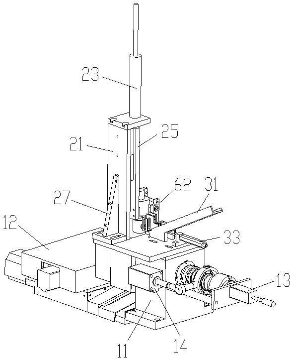
[0037] Figures 1 to 10 It is a structural representation of the present invention.

[0038] The reference signs are: control cabinet G, punching machine main body 1, clamping workpiece and rotating spindle device 11, cross table 12, material return cylinder 13, clamping cylinder 14, material storage tank 15, lifting device 2, Lifting bracket 21, lifting guide rail 22, lifting cylinder 23, guide rail slider 24, lifting slide plate 25, pin shaft 26, reinforcement plate 27, automatic feeding device 3, feeding guide rail 31, feeding chute 31a, guide rail base 32, Feeding port 32a, feeding cylinder 33, feeding cylinder bracket 34, rotating manipulator 4, receiving hole 4a, cutout 4b, concave surface 4c, connecting sleeve 41, rotator 5, rotator bracket 51, ejector device 6, Material jacking cylinder 61, material jacking connecting plate 62, materi...


PUM


Abstract

The invention discloses an automatic feeding and automatic turning-round magnetic punching machine. The automatic feeding and automatic turning-round magnetic punching machine comprises a punching machine main body composed of a clamping workpiece and rotating main shaft device, a cross worktable, a discharging air cylinder and a clamping air cylinder, and a lifting device and an automatic feedingdevice used for pushing a to-be-machined material into a rotating mechanical arm are arranged on the upper plate surface of the clamping workpiece and rotating main shaft device; and the rotating mechanical arm is fixedly installed on a rotator, the rotator rotates to drive the rotating mechanical arm to rotate so as to achieve the automatic turning-round of the to-be-machined material, the rotator is installed on the lifting device, the lifting device drives the rotator to achieve the conveying of the to-be-machined material to a position with a predetermined height, a material ejecting device is further installed on the lifting device, and the material ejecting device moves horizontally to push the to-be-machined material in the rotating mechanical arm to a clamping position of the clamping workpiece and rotating main shaft device. The automatic feeding and automatic turning-round magnetic punching machine is high in punching efficiency and low in production cost, and twice machining of the material can be conducted in the same environment.

Description

technical field [0001] The invention belongs to the technical field of mechanical processing, in particular to a punching machine for punching magnetic materials, specifically an automatic feeding and automatic turning magnetic material punching machine. Background technique [0002] At present, due to their material characteristics, magnetic materials such as NdFeB, SmCo, etc., are generally drilled twice. If they are pierced at one time, it is easy to cause chipping or breakage of the product. Therefore, the magnetic material punching machines on the market can only punch one end of a batch of materials first, and the semi-finished products after punching one end need to be collected manually, and then reloaded to punch the other end. The disadvantages of this operation are: [0003] 1. The machining accuracy is low. In the second machining process, the product cannot be guaranteed to be carried out in the same environment as the first machining (such as: the same processi...

Claims


Application Information

Patent Timeline
Patent Type & Authority Applications(China)
IPC IPC(8): B23B41/00B23Q7/00B23Q7/04
CPCB23B41/00B23Q7/00B23Q7/005B23Q7/006B23Q7/04
Inventor 王有富
Owner 宁波市江北宁科金创机械制造有限公司
Why Eureka
Try Eureka