Veneer continuous tooth jointing machine

A tooth joint and veneer technology, which is applied in the field of wood processing, can solve the problems of low production efficiency, easy breakage of tooth joint interface, poor splicing effect, etc., and achieve good pressing effect, smooth movement and good tooth joint effect

Pending Publication Date: 2020-06-26
山东昶兴智能科技有限公司
View PDF1 Cites 3 Cited by
  • Summary
  • Abstract
  • Description
  • Claims
  • Application Information

AI Technical Summary

Problems solved by technology

[0002] At present, in the production process of multi-layer plywood, vertical veneer is a necessary raw material for the mechanical structure of plywood. Due to the influence of fast-growing forest timber diameter and material utilization rate, it is impossible to produce a complete vertical veneer that meets the size requirements of plywood. , traditional veneer longitudinal butt joint equipment generally has problems such as low production efficiency, automatic splicing cannot be realized, poor splicing effect (such as uneven splicing gaps, overlapping seams), and splicing methods that do not conform to the mechanical structure of plywood, which seriously affect the composite The automation process of plywood production restricts the development of plywood enterprises and the improve

Method used


Image

  • Veneer continuous tooth jointing machine
  • Veneer continuous tooth jointing machine
  • Veneer continuous tooth jointing machine

Examples


Embodiment 1

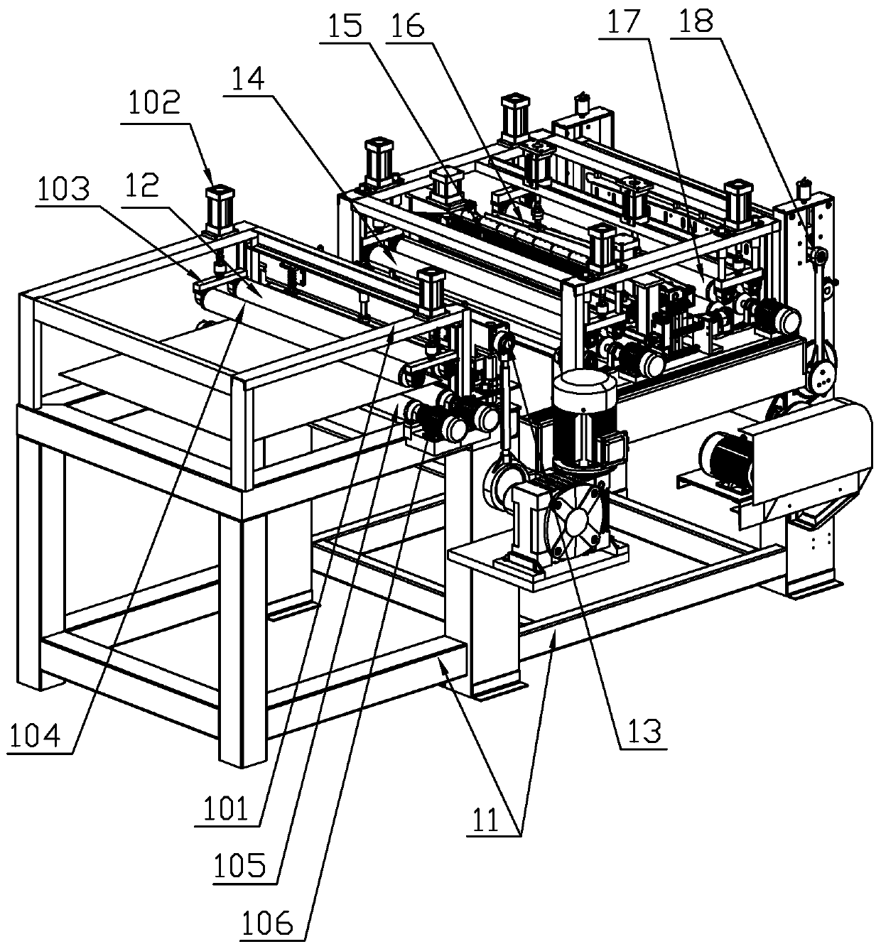
[0035] A single-board continuous tooth splicing machine, comprising a frame 11, a feeding mechanism 12, a comb tooth mechanism 13, a forward docking mechanism 14, a gluing mechanism 15, a pressing mechanism 16, and a rear transmission mechanism 17; There is a feeding mechanism 12, one side of the feeding mechanism 12 is provided with a comb mechanism 13, one side of the comb mechanism 13 is provided with a forward docking mechanism 14, a side of the forward docking mechanism 14 is provided with a gluing mechanism 15, and a side of the gluing mechanism 15 is provided There is a pressing mechanism 16, and a rear transmission mechanism 17 is provided on one side of the pressing mechanism 16.

[0036] The feeding mechanism 12 includes a feeding bracket 101, a cylinder I 102, a connecting plate I 103, a lower pressure roller I 104, a conveying roller I 105, and a motor I 106. The feeding bracket 101 is provided with a pair of cylinders I 102, and the head of the cylinder I 102 is provi...

Embodiment 2

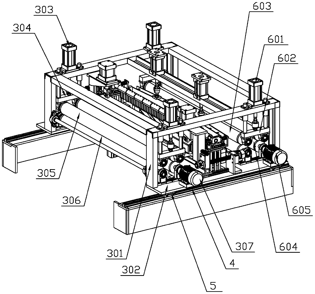
[0046] Compared with the first embodiment, the difference is that: the forward docking mechanism 14 and the pressing mechanism 16 are provided with a docking adjustment mechanism. The docking adjustment mechanism includes a base beam 701, a slider II705, a guide rail II706, and a wire sleeve fixing Seat 707, screw sleeve 708, screw 709, screw bracket 7091, stop 7092, timing belt wheel 710, timing belt 711, motor Ⅳ 712, support block Ⅱ 713, butt adjustment bracket 714, butt adjustment cylinder 715, lower pressing block Ⅱ 716 The upper part of the base beam 701 is provided with a supporting block II 713, both ends of the supporting block II 713 are provided with a docking adjustment bracket 714, the docking adjustment bracket 714 is provided with a docking adjustment cylinder 715, and the head of the docking adjustment cylinder 715 is provided with a lower pressing block II 716; The bottom of the base beam 701 is provided with a slider II705, the bottom of the slider II705 is prov...

Embodiment 3

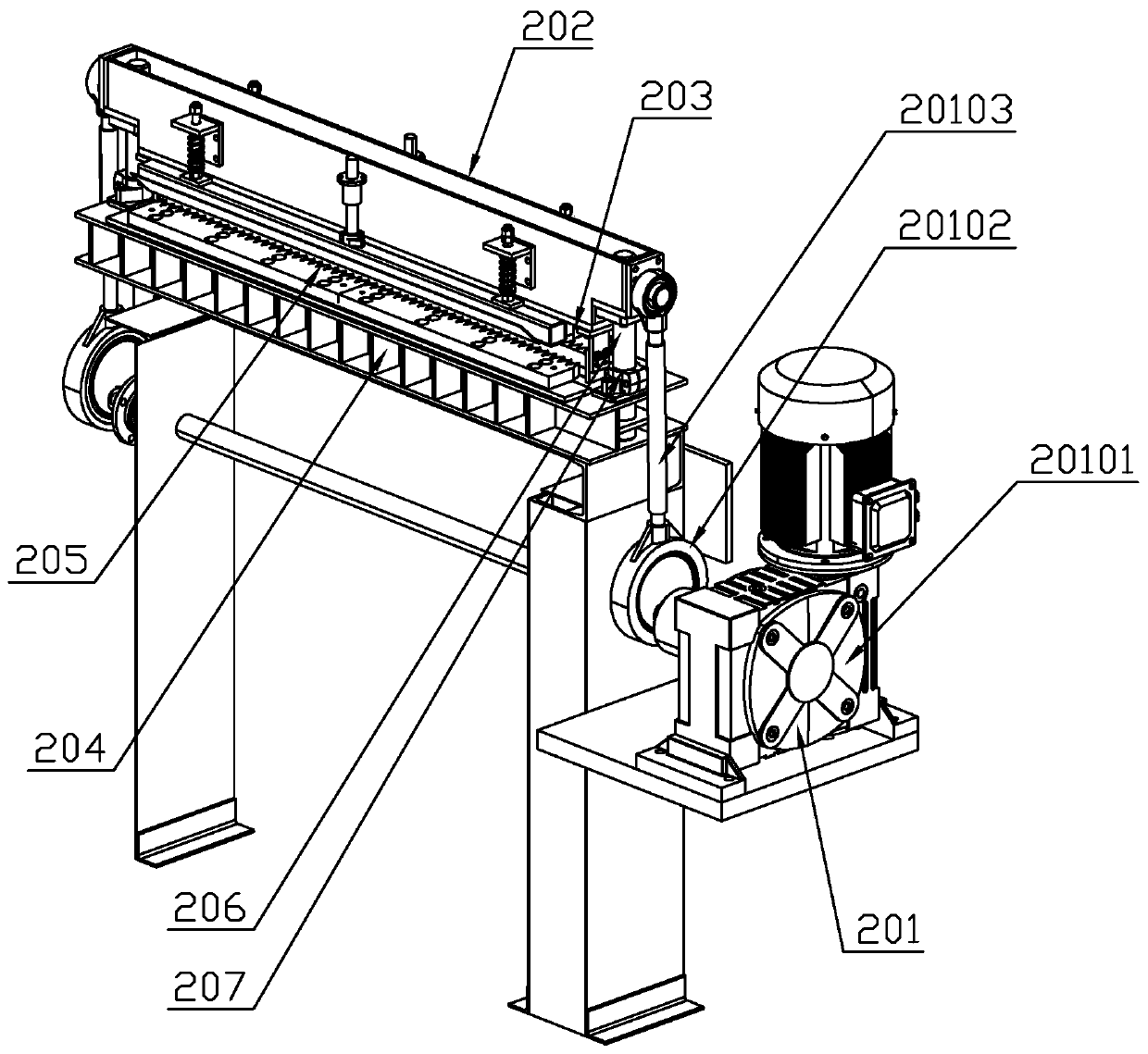
[0050] Compared with Embodiment 1, the difference is: the feeding mechanism 12 is provided with a 90° steering mechanism 2 on one side, and the 90° steering mechanism 2 is provided with a splicing machine 1 on one side, and the tail of the sizing mechanism 18 is connected by a conveyor belt for stacking Mechanism 3, in order to increase the utilization rate of veneers, small veneers are spliced ​​horizontally by a splicing machine, and after a 90° turn, they enter the continuous gear splicing machine for longitudinal splicing.


PUM


Abstract

The invention discloses a veneer continuous tooth jointing machine. The machine comprises a rack, a feeding mechanism, a tooth combing mechanism, a front conveying butt joint mechanism, a gluing mechanism, a pressing mechanism and a rear conveying mechanism, wherein the feeding mechanism is arranged on the upper portion of the rack, the tooth combing mechanism is arranged on one side of the feeding mechanism, the front conveying butt joint mechanism is arranged on one side of the tooth combing mechanism, the gluing mechanism is arranged on one side of the front conveying butt joint mechanism,the pressing mechanism is arranged on one side of the gluing mechanism, and the rear conveying mechanism is arranged on one side of the pressing mechanism. According to the machine, butt joint is completed in the conveying process, the action is smooth, the efficiency is high, a cooling press-fit mode is face-to-face contact press-fit, the press-fit effect is good, and the strength of a tooth joint is high.

Description

Technical field [0001] The invention belongs to the technical field of wood processing, and particularly relates to a veneer continuous tooth splicing machine. Background technique [0002] At present, in the production process of multi-layer plywood, vertical veneer is a necessary raw material for the mechanical structure of plywood. Affected by the size of fast-growing forest wood and material utilization rate, it is impossible to produce integrated vertical veneer that meets the size requirements of plywood. , Traditional veneer vertical butting equipment generally has low production efficiency, cannot realize automatic splicing, poor splicing effects (such as uneven splicing gaps, staggered overlap), and splicing methods that do not conform to the mechanical structure of plywood, which seriously affect the composite The process of automatic board production has restricted the development of plywood enterprises and the improvement of product quality. [0003] After searching, t...

Claims


Application Information

Patent Timeline
IPC IPC(8): B27D1/10B27D3/00B27C5/02B27F5/02B27G11/00B65G47/52
CPCB27C5/02B27D1/10B27D3/00B27F5/02B27G11/00B65G47/52
Inventor 李皓赵紫伟张华兵
Owner 山东昶兴智能科技有限公司
Why Eureka
Try Eureka