Well testing blocking fork
A technology of well testing and fixing seat, which is applied in the direction of wellbore/well components, earthwork drilling and production, etc. It can solve the problems of poor flexibility, single use, and inability to adjust the opening size, so as to reduce labor intensity, simple structure, and improve the convenience of use sexual effect
- Summary
- Abstract
- Description
- Claims
- Application Information
AI Technical Summary
Problems solved by technology
Method used
Image
Examples
Embodiment 1
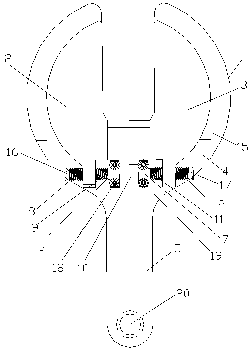
[0031] see figure 1 , a well testing retaining fork, including a body 1, and also includes a rotating shaft, a first movable block 2 and a second movable block 3, the body 1 is in the shape of a "Y", and the body 1 includes a mounting section 4 and a gripping section 5 , the mounting section 4 is fixedly connected with a first fixed seat 6 and a second fixed seat 7, the rotating shaft is a cylinder, the rotating shaft is threadedly connected with the first fixed seat 6 and the second fixed seat 7, and the rotating shaft It includes a positive thread segment 8, a first optical axis segment 9, a knurl segment 10, a second optical axis segment 11 and a reverse thread segment 12 in sequence, and the knurled segment 10 is located between the first optical axis segment 9 and the second optical axis segment 11, the rotating shaft runs through the first fixed seat 6 and the second fixed seat 7, the positive thread section 8 is threaded with the first movable block 2, and the reverse t...
Embodiment 2
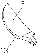
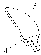
[0034] see Figure 1-Figure 3, a well testing retaining fork, including a body 1, and also includes a rotating shaft, a first movable block 2 and a second movable block 3, the body 1 is in the shape of a "Y", and the body 1 includes a mounting section 4 and a gripping section 5 , the mounting section 4 is fixedly connected with a first fixed seat 6 and a second fixed seat 7, the rotating shaft is a cylinder, the rotating shaft is threadedly connected with the first fixed seat 6 and the second fixed seat 7, and the rotating shaft It includes a positive thread segment 8, a first optical axis segment 9, a knurl segment 10, a second optical axis segment 11 and a reverse thread segment 12 in sequence, and the knurled segment 10 is located between the first optical axis segment 9 and the second optical axis segment 11, the rotating shaft runs through the first fixed seat 6 and the second fixed seat 7, the positive thread section 8 is threaded with the first movable block 2, and the ...
Embodiment 3
[0038] see Figure 1-Figure 3 , a well testing retaining fork, including a body 1, and also includes a rotating shaft, a first movable block 2 and a second movable block 3, the body 1 is in the shape of a "Y", and the body 1 includes a mounting section 4 and a gripping section 5 , the mounting section 4 is fixedly connected with a first fixed seat 6 and a second fixed seat 7, the rotating shaft is a cylinder, the rotating shaft is threadedly connected with the first fixed seat 6 and the second fixed seat 7, and the rotating shaft It includes a positive thread segment 8, a first optical axis segment 9, a knurl segment 10, a second optical axis segment 11 and a reverse thread segment 12 in sequence, and the knurled segment 10 is located between the first optical axis segment 9 and the second optical axis segment 11, the rotating shaft runs through the first fixed seat 6 and the second fixed seat 7, the positive thread section 8 is threaded with the first movable block 2, and the...
PUM
 Abstract
Description
Claims
Application Information
 - R&D
- Intellectual Property
- Life Sciences
- Materials
- Tech Scout
- Unparalleled Data Quality
- Higher Quality Content
- 60% Fewer Hallucinations
Browse by: Latest US Patents, China's latest patents, Technical Efficacy Thesaurus, Application Domain, Technology Topic, Popular Technical Reports.
© 2025 PatSnap. All rights reserved.Legal|Privacy policy|Modern Slavery Act Transparency Statement|Sitemap|About US| Contact US: help@patsnap.com


