Ultrasonic flow measurement method and device

A flow measurement device and flow measurement technology, applied in the ultrasonic field, can solve problems such as increasing system complexity, increasing flow measurement error, and large number of side tones, so as to avoid inconsistent probe frequencies, ensure measurement range, and shorten response time Effect

Active Publication Date: 2020-06-26
NAT UNIV OF DEFENSE TECH
View PDF5 Cites 0 Cited by
  • Summary
  • Abstract
  • Description
  • Claims
  • Application Information

AI Technical Summary

Problems solved by technology

[0005] For the pulse wave measurement method, the inconsistency of the probe (probes produced in the same batch will also exist) will cause the difference in the impulse response, and the change of the external environment will aggravate the inconsistency of the spectral response of the probe, resulting in unavoidable measurement errors.
On the other hand, the lower energy conversion under the pulse wave system makes the SNR of the acoustic signal lower, thereby increasing the measurement error of the flow rate
The continuous wave system better solves the difficulties of the pulse wave system, but it also brings the problem of measurement ambiguity
The continuous wave measurement method based on sidetone (sound waves of multiple frequencies) proposed in the prior art can better solve the problem of measurement ambiguity, but requires a large number of sidetones, which increases the complexity of the system

Method used


Image

  • Ultrasonic flow measurement method and device
  • Ultrasonic flow measurement method and device
  • Ultrasonic flow measurement method and device

Examples


Embodiment 1

[0069] Example 1: Ultrasonic flow measurement method

[0070] In order to solve the problem that the measurement response time caused by multiple frequencies is slow, the embodiment of the present invention only uses one frequency (generally the highest frequency is taken, and this frequency is generally set to the resonant frequency of the ultrasonic probe, or a frequency close to the resonant frequency of the ultrasonic probe. ) to achieve the above measurement problem.

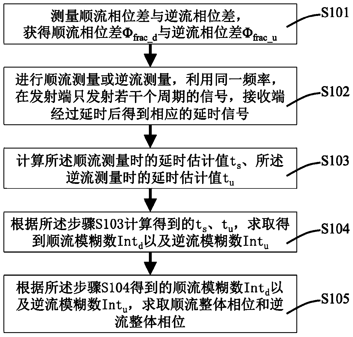
[0071] Specifically, please refer to the flowchart image 3 shown. An ultrasonic flow measurement method, comprising the following steps:

[0072] S101: Measure the downstream phase difference and the upstream phase difference to obtain the downstream phase difference Φ frac_d Phase difference Φ with reverse flow frac_u ;

[0073] S102: Perform downstream measurement or countercurrent measurement, using the same frequency, only transmit signals of several cycles at the transmitting end, and the receivi...

Embodiment 2

[0091] Example 2: Ultrasonic flow measurement device

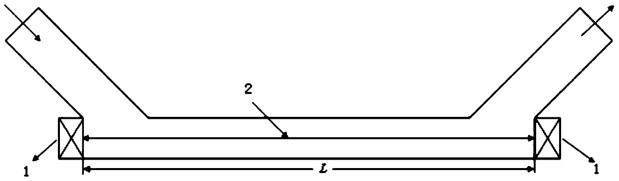
[0092] For the embodiments of the present invention, please refer to Image 6 As shown, an ultrasonic flow measurement device includes:

[0093] Phase difference measurement module 3, used to measure the downstream phase difference and the upstream phase difference, and obtain the downstream phase difference Φ frac_d Phase difference Φ with reverse flow frac_u ;

[0094] Ultrasonic detection module, the ultrasonic probe has a transmitting end 4 and a receiving end 5, the transmitting end 4 is used to transmit only several cycles of signals using the same frequency, and the receiving end 5 is used to receive the corresponding signal after a delay. delay signal;

[0095] Delay estimation value calculation module 6, used to calculate the delay estimation value t during downstream measurement s , the estimated delay value t during downstream measurement u ;

[0096] The fuzzy number obtaining module 7 is used for calcul...


PUM


Abstract

The invention discloses an ultrasonic flow measurement method and device. The method is characterized by comprising the following steps: S101, measuring a forward flow phase difference and a reverse flow phase difference, and obtaining a forward flow phase difference phi <fac_d> and a reverse flow phase difference phi <fac_u>; s102, forward flow measurement or reverse flow measurement is carried out, the same frequency is utilized, only a plurality of periods of signals are transmitted at the transmitting end, and the receiving end obtains corresponding delay signals after time delay; s103, calculating a time delay estimated value ts during forward flow measurement and a time delay estimated value tu during reverse flow measurement; s104, according to ts and tu obtained through calculationin the step S103, obtaining a forward flow fuzzy number Intd and a reverse flow fuzzy number Intu through calculation; and S105, according to the forward flow ambiguity number Intd and the reverse flow ambiguity number Intu obtained in the step S104, solving a forward flow overall phase and a reverse flow overall phase. Compared with a continuous wave measurement method based on a sidetone mode in the prior art, the continuous wave measurement method based on the sidetone mode has the advantages that voice waves of multiple frequencies need to be adopted, high-precision measurement can be obtained through the continuous wave method while the measurement range is guaranteed only through the voice wave of one frequency, measurement is more convenient, and the measurement reaction time is shortened.

Description

technical field [0001] The present invention relates to the field of ultrasonic technology, in particular to an ultrasonic flow measurement method and device. Background technique [0002] The ultrasonic flowmeter utilizes the significant difference between the forward and reverse propagation of sound waves in the pipeline flow, and obtains the information of the average flow velocity of the pipeline by processing the sound wave signal, and then predicts the flow rate of the pipeline flow. Ultrasonic flow meters have the advantages of not invading the measured fluid, having no moving parts, and not affecting the fluid flow, so they are widely used in various industrial fields. In the aerospace field, Matthijssen and Van Put developed an ultrasonic flowmeter for ESA based on pulse wave system for space pipeline measurement, and as a payload, it has been carried on the Alphabus communication satellite launched by ESA in July 2013 superior. [0003] In the pulse wave system, ...

Claims


Application Information

Patent Timeline
Patent Type & Authority Applications(China)
IPC IPC(8): G01F1/66
CPCG01F1/66
Inventor 陈勇张若凡尹政龙张翔吴宗谕
Owner NAT UNIV OF DEFENSE TECH
Why Eureka
Try Eureka