Eureka AIR delivers breakthrough ideas for toughest innovation challenges, trusted by R&D personnel around the world.

Low dropout linear regulator with high power supply rejection ratio

A technology with high power supply rejection ratio and low-dropout linearity, which is applied in the direction of instruments, electric variable adjustment, control/regulation systems, etc., can solve the problems of error amplifier output voltage increase, low-dropout linear regulator circuit output voltage instability, low-voltage Poor linear regulator circuit power supply rejection ratio and other issues, to achieve the effect of small power supply ripple

Active Publication Date: 2020-06-26
UNIV OF ELECTRONICS SCI & TECH OF CHINA +1
View PDF4 Cites 9 Cited by
  • Summary
  • Abstract
  • Description
  • Claims
  • Application Information

AI Technical Summary

Problems solved by technology

[0003] However, when the output voltage Vout of the traditional low-dropout linear regulator circuit increases, the feedback voltage after passing through the resistor divider feedback network will also increase, resulting in an increase in the output voltage of the error amplifier, making the low-dropout linear regulator circuit The output voltage is unstable
In addition, in the traditional low-dropout linear regulator circuit, the ripple and noise on the power supply flow into the load and couple to the gate terminal of the power transistor through the power transistor, and then convert the large transconductance of the power transistor into the current of the output terminal and flow into the load. , which has a large impact on the power supply rejection ratio of the low dropout linear regulator circuit

Method used


Image

  • Low dropout linear regulator with high power supply rejection ratio
  • Low dropout linear regulator with high power supply rejection ratio
  • Low dropout linear regulator with high power supply rejection ratio

Examples


Embodiment Construction

[0037] The technical scheme of the present invention will be described in detail below in conjunction with the accompanying drawings and embodiments.

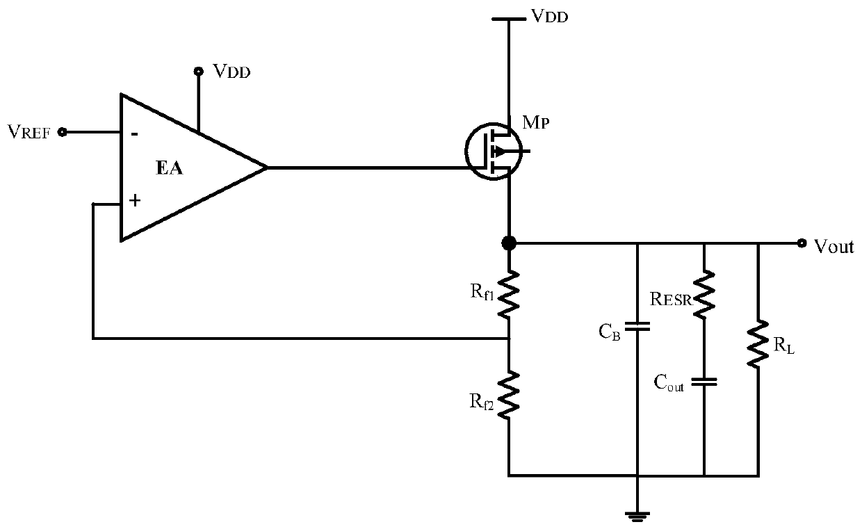
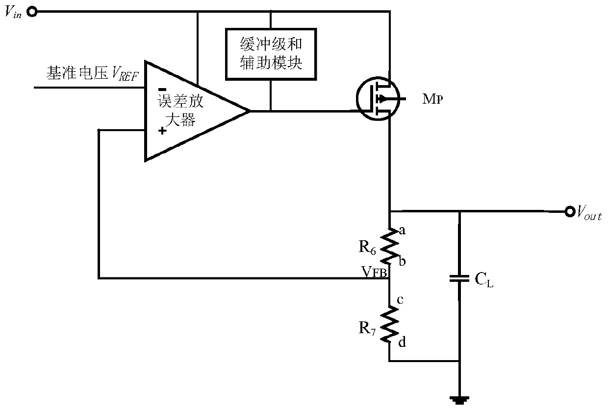
[0038] The present invention proposes a low-dropout linear regulator with high power supply rejection ratio, including an error amplifier, a power switch tube, and a first feedback resistor R 6 , the second feedback resistor R 7 and the first capacitor C L , the inverting input of the error amplifier is connected to the reference voltage V REF , its output end is connected to the control end of the power switch tube; both ends of the power switch tube are respectively connected to the power supply voltage V DD and the output of the low dropout linear regulator; the first feedback resistor R 6 and the second feedback resistor R 7 A feedback network is formed and connected in series between the output terminal of the low-dropout linear regulator and the ground, and its series point is connected to the non-inverting input term...


PUM


Abstract

The invention discloses a low dropout linear regulator with a high power supply rejection ratio. An auxiliary module and a buffer stage are connected to the output end of the error amplifier and the control end of the power switch tube; in the auxiliary module, a power switch tube is scaled down and copied to obtain a first switch tube, the current flowing through a first direct current source ofthe first switch tube and a second switch tube form a current mirror structure, and the current mirrored by the second switch tube generates voltage drop on a first resistor to obtain an auxiliary voltage signal to be connected with the inverting input end of a first operational amplifier; the first operational amplifier, the second resistor and the third resistor form a proportional amplificationcircuit to process the auxiliary voltage signal and output the auxiliary voltage signal to the buffer stage; when the grid voltage of the power switch tube rises or falls, the buffer stage reduces orincreases the load current flowing through the power switch tube, so that the output voltage of the low dropout regulator drops or rises, and the change of the output voltage is offset; and the gridvoltage of the power switch tube does not change along with the change of power ripples, so that a high power supply rejection ratio is realized.

Description

technical field [0001] The invention belongs to the technical field of electronic circuits and relates to a low-dropout linear regulator circuit with high power supply rejection ratio. Background technique [0002] Such as figure 1 Shown is a traditional low-dropout linear regulator circuit, which is usually placed in front of the power receiving unit. A typical low-dropout linear regulator structure generally consists of a voltage reference source VREF, an error amplifier EA, a power transistor MP, and a feedback network Rf1 and Rf2 composition. Its working principle is as follows: use the negative feedback system to sample the output voltage, then compare it with the reference voltage, and stabilize the output voltage Vout through loop adjustment. The error amplifier EA is used to compare the sampling voltage with the reference voltage; the power transistor is the channel through which the load current flows, and its conduction is controlled through a negative feedback l...

Claims


Application Information

Patent Timeline
Patent Type & Authority Applications(China)
IPC IPC(8): G05F1/56
CPCG05F1/56
Inventor 李靖陈昱桦田明吕景昊宁宁于奇
Owner UNIV OF ELECTRONICS SCI & TECH OF CHINA
Why Eureka
Eureka Blog
Learn More