Capillary microfluidic reactor with controllable fixed area of ​​catalytic material and preparation method

A technology of catalytic materials and fixed areas, applied in chemical instruments and methods, chemical/physical/physical chemical reactors, chemical/physical processes, etc., can solve the problem that small volumes cannot meet large-scale production needs, and materials cannot be fixed in capillaries Problems such as the inner wall and uncontrollable material area, etc., to achieve good fixing effect, good and consistent catalytic effect, and stable reaction

Active Publication Date: 2021-10-01
QILU UNIV OF TECH
View PDF8 Cites 0 Cited by
  • Summary
  • Abstract
  • Description
  • Claims
  • Application Information

AI Technical Summary

Problems solved by technology

The applicable photocatalytic materials in this way have relatively large limitations, and it is impossible to control the area where the materials are fixed, which reduces the utilization rate of the materials.
[0008] At present, microfluidic reactors have the following disadvantages: ①Its small volume cannot meet the needs of large-scale production. In order to increase the throughput, the common solution is to expand the microfluidic reactor or create more parallel channels, and this method will increase the cost
[0010] The above scheme has the following disadvantages: (1) Synthesize and fix the catalytic material on the inner wall of the capillary, and cannot fix the prepared material on the inner wall of the capillary. The method used in this scheme is not suitable for most catalytic materials
(2) What this solution achieves is to fix the catalytic material on the inner wall of the capillary indiscriminately, the fixed area is uncontrollable, and the utilization rate of the catalytic material is low
(3) The production process of this scheme is complicated, the cost is high, and it is difficult to scale up

Method used


Image

  • Capillary microfluidic reactor with controllable fixed area of ​​catalytic material and preparation method
  • Capillary microfluidic reactor with controllable fixed area of ​​catalytic material and preparation method

Examples


example 1

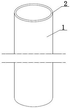
[0034] The reactor preparation method in this example is used to prepare a full-area capillary microfluidic reactor, including the following steps:

[0035] (1) PDMS prepolymer and curing agent are prepared in a mass ratio of 5:1-30:1 to prepare PDMS liquid, stir and mix with a clean glass rod, and stir for 5-10 minutes. The ratio of PDMS prepolymer and curing agent preparation will affect the viscosity of the prepared PDMS liquid, and the PDMS liquid prepared by the aforementioned ratio has the viscosity of sticking capillary and powder.

[0036] (2) Put the mixed PDMS liquid into a vacuum desiccator, and use a vacuum pump to remove the air bubbles in the liquid. The air bubbles in the liquid will affect the coating effect of PDMS on the inner wall of the capillary. The vacuuming time is 10-20 minutes. The prepared mixed PDMS liquid was stored in a -20°C refrigerator for later use.

[0037] (3) Take a clean and dry round glass capillary with a diameter of 0.3-1.1mm. Pick up...

example 2

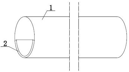
[0041] The reactor preparation method in this example is used to prepare a capillary microfluidic reactor in a partial area, including the following steps:

[0042] (1) Prepare PDMS liquid with PDMS prepolymer and curing agent at a ratio of 5:1-30:1, stir and mix with a clean glass rod, and stir for 5-10 minutes.

[0043] (2) Put the mixed PDMS liquid into a vacuum desiccator, and use a vacuum pump to remove the air bubbles in the liquid. The air bubbles in the liquid will affect the coating effect of PDMS on the inner wall of the capillary. The vacuuming time is 10-20 minutes. The prepared mixed PDMS liquid was stored in a -20°C refrigerator for later use.

[0044] (3) Take a clean and dry round glass capillary with a diameter of 0.3-1.1mm. Pick up an appropriate amount of PDMS liquid with a clean syringe needle, fill it from one end of the capillary until the length of the PDMS liquid column in the capillary is 1.1-4.4mm, and the length of the capillary is 11cm. Fix the ca...


PUM

PropertyMeasurementUnit
diameteraaaaaaaaaa

Abstract

The invention discloses a capillary microfluidic reactor with a controllable fixed area of ​​catalytic material and a preparation method thereof, comprising the following steps: (1) coating a layer of PDMS liquid on a specified wall area of ​​the capillary, and the capillary is airtight and transparent (2) Feed the required fixed powdered catalytic material into the capillary, part of the catalytic material adheres to the PDMS liquid coating, and the excess catalytic material flows out of the capillary; (3) The PDMS liquid is solidified and the PDMS layer is The adhered catalytic material is immobilized. Thus, a capillary microfluidic reactor with a controllable fixed area of ​​the catalytic material can be obtained. The present invention can control the coating area of ​​PDMS on the inner wall of the capillary by adjusting the coating conditions, and the capillary wall has no air-permeable characteristics, avoiding the gas-permeable PDMS layer. The concentration of the reaction solution is changed so that the reaction is stable.

Description

technical field [0001] The invention relates to a photocatalytic reactor, and also relates to a preparation method of the photocatalytic reactor. Background technique [0002] Photocatalytic technology is a highly efficient and safe catalytic technology using solar energy. It is clean, renewable and environmentally friendly. play an important role. However, its low catalytic efficiency is currently the bottleneck of its application. In the case of constant photocatalytic materials, the photocatalytic reaction efficiency is mainly limited by the design of the reactor. The distribution and transmission of light in the reactor, and the transfer of reactants in the reactor play a crucial role in the reaction rate. Optimizing the design of the reactor is very important to realize the full utilization of solar energy and high-efficiency catalysis. [0003] Microfluidic chip, also called lab-on-a-chip, is the miniaturization and integration of many basic functions of convention...

Claims


Application Information

Patent Timeline
Patent Type & Authority Patents(China)
IPC IPC(8): B01J8/00B01J8/02B01J19/00
CPCB01J8/008B01J8/0292B01J19/0093B01J2208/00884B01J2219/00835
Inventor 黄晓文黄子煜王培仑陈成敏王磊林惠超
Owner QILU UNIV OF TECH
Why Eureka
Try Eureka