Automatic sponge nail file production equipment and process thereof

An automatic production and nail file technology, applied in manicure or pedicure tools, clothing, devices for applying liquid to the surface, etc., can solve the problems of slow production efficiency, high labor demand and poor quality, etc. achieve the effect of improving production efficiency

Inactive Publication Date: 2020-07-03
宋凤华
View PDF0 Cites 3 Cited by
  • Summary
  • Abstract
  • Description
  • Claims
  • Application Information

AI Technical Summary

Problems solved by technology

However, there are many defects in this process: 1. The production efficiency is slow and the labor demand is large
2. The amount of glue applied manually cannot be controlled, and the glue is prone to overflow during pressing operations, resulting in poor quality

Method used


Image

  • Automatic sponge nail file production equipment and process thereof
  • Automatic sponge nail file production equipment and process thereof
  • Automatic sponge nail file production equipment and process thereof

Examples


Embodiment 1

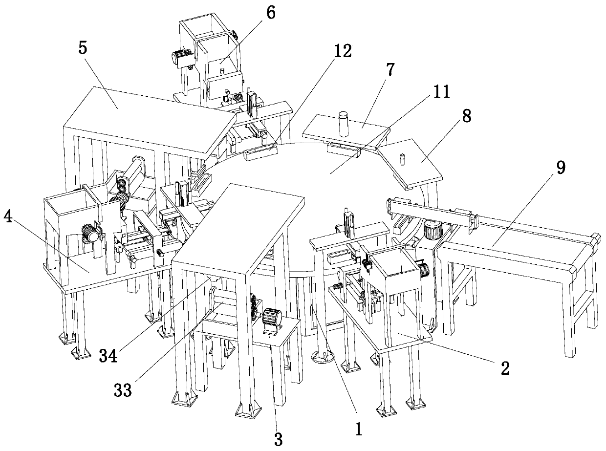
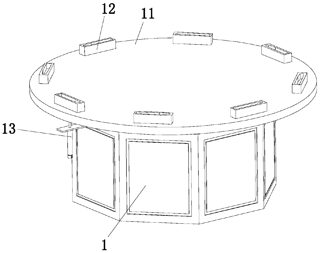
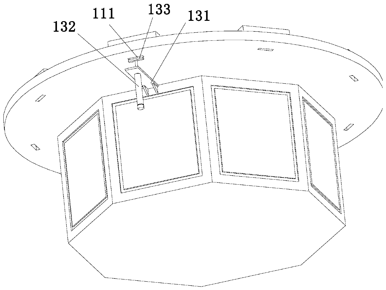
[0041] Combine below Figure 1 to Figure 17 As shown, the embodiment of the present invention provides automatic production equipment for sponge nail files, including a workbench 1, which is provided with a stepper motor with the output end facing upwards, and the output end of the stepper motor is installed with a A turntable 11 arranged horizontally. The turntable 11 is provided with a number of fixtures 12 arranged at equal angles along its circumference. A first feeding device 2 and a first gluing device are arranged in turn along the rotation direction of the turntable 11. 3. The second feeding device 4, the second gluing device 5, the third feeding device 6, the pressing device 7, the drying device 8 and the unloading device 9, the outer wall of the workbench 1 is provided with a The ejector assembly 13 matched with the feeding device 9; when the present invention is working, the file body is first placed in the first feeding device 2 and the third feeding device 6 respe...

Embodiment 2

[0057] The technique of the sponge nail file automatic production equipment described in embodiment 1, comprises the following steps:

[0058]Step 1. First, the stepper motor drives the turntable 11 to perform step-by-step rotation, and all the fixtures 12 on the turntable 11 also rotate simultaneously with it. When rotating, the first file is first passed through the first feeding device 2 Put the body into the fixture 12, drive the driving gear 243 through the anti-blocking motor 242, the driving gear 243 drives the driven gear 244 and the installation rod 245 to rotate around the axis of the installation rod 245, and the shaking part 246 is synchronized with the installation rod 245 Rotate, the shaking member 246 resists the shaking plate 241 to produce a shaking effect when rotating, and the file body in the discharge frame 22 can shake and enter the extension plate 224 and the inner bottom wall of the discharge frame 22 along the inner bottom wall of the discharge frame 22...


PUM


Abstract

The invention discloses automatic sponge nail file production equipment. The invention belongs to the field of medical care product production. The production equipment comprises a workbench, a stepping motor with an upward output end is arranged in the workbench; a horizontally arranged rotary disc is mounted at the output end of the stepping motor; a plurality of placing jigs which are arrangedat equal angles in the circumferential direction of the rotary disc are arranged on the rotary disc; a first feeding device, a first gluing device, a second feeding device, a second gluing device, a third feeding device, a pressing device, a blow-drying device and a discharging device are sequentially arranged in the rotating direction of the rotary disc, and an ejection assembly matched with thedischarging device is arranged on the outer wall of the workbench. According to the automatic sponge nail file production equipment, automatic production of sponge nail files is achieved, the production efficiency is improved, automatic gluing operation is achieved through cooperation of a gluing assembly and a gluing assembly, glue applied to the tops of file bodies or the tops of connecting pieces is appropriate in thickness and uniform in distribution, and the situation that the glue overflows during pressing is avoided.

Description

technical field [0001] The invention relates to the field of production of medical care products, in particular to automatic production equipment and technology of sponge nail files. Background technique [0002] With the advent of the aging society, the market for elderly care in hospitals and nursing homes is getting bigger and bigger, with huge market potential. After the elderly or elderly patients have trimmed their nails, they still need to take care of their nails. For the elderly or elderly patients Nail care needs to be very careful and careful, so suitable tools are needed, and the sponge nail file is a nail tool used for trimming, shaping and polishing of real nails, fake nails, crystal nails or toenails. , good practicability. The sponge nail file includes clips and two file bodies. The processing steps of the traditional sponge nail file are as follows: the first step, the worker places a file body in the positioning jig; the second step, the worker applies gl...

Claims


Application Information

Patent Timeline
Patent Type & Authority Applications(China)
IPC IPC(8): A45D29/04B05C1/02B05C11/10B05C13/02B05C21/00
CPCA45D29/04B05C1/02B05C11/1002B05C13/02B05C21/00
Inventor 宋凤华
Owner 宋凤华
Why Eureka
Try Eureka